I have taken some time to better study the wheel alignment on the Duracraft VS-312 bandsaw.
The wheel axles are in 10mm bearings with the wheels nominally 1 inch wide (25.4mm). The axle pins screw directly into the bandsaw casings.
The left photo below shows the mounting hole in the saw casing, and on the right is a photo of the axle pin partially screwed in.
click to enlarge

The photo below shows an axle pin
click to enlarge

Below is a diagram of the axle pin, showing dimensions:
click to enlarge

- A slotted screw head
- A snap ring the holds the outer wheel bearing
- A shoulder to the bearing formed by a 6 mm OD 1mm wide recess
- M8 screw threads that screw into the bandsaw casing.
The photo below shows the axle pin installed through a wheel bearing. The wheel bearing is about 1mm narrower than the bearing area on the pin, as is noted in the photo. This results in 1mm on axial play in the bearing, which I reduced by putting a total of 0.7mm of shim washers between the snap ring and the outer side of the wheel bearing.
click to enlarge

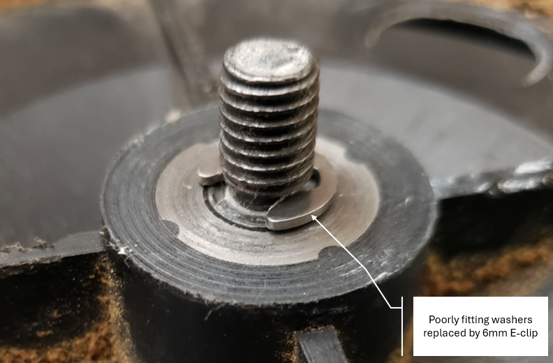
As I originally found the bandsaw, it had two 5/16" washers installed between the saw casing and the pin's bearing shoulder as shown in the photo below. The washers had a large ID, giving a loose fit around the threads. Also, because of the 6mm slot next to the shoulder, the washers seated poorly when installed. The washers move the wheels outward away from the case by 3mm, which caused the gear wheel of the motor to be far out on the end of the motor axle.
click to enlarge

I ordered a metric E-clip assortment and replaced the poorly fitting washers with a 6 mm E-clip. I am convinced that this was the way the axles were originally designed to be configured. The E-clip fits in the slot in the pin and seats well. The distance between the inner side of the wheel and the shoulder on the pin is now reduced to 1mm, moving the drive gear on the motor inwards by 2mm.
click to enlarge
Another problem I found was that the upper wheel didn't have any washers installed. This results in a 3mm misalignment of the upper wheel in relation to the lower wheels. As designed, the upper wheel has fixed alignment with the other two wheels, but has an adjustment of angular alignment to position the saw blade. So the 3mm misalignment was likely causing binding when the blade turns. I have now installed the proper E-clip in all three wheels and I think I should get good alignment of the three wheels with much less friction than before.
No comments:
Post a Comment