Tuesday, January 31, 2023

QRP 10W PA (5): interface to Tuna Tin S (updated with output spectrum)

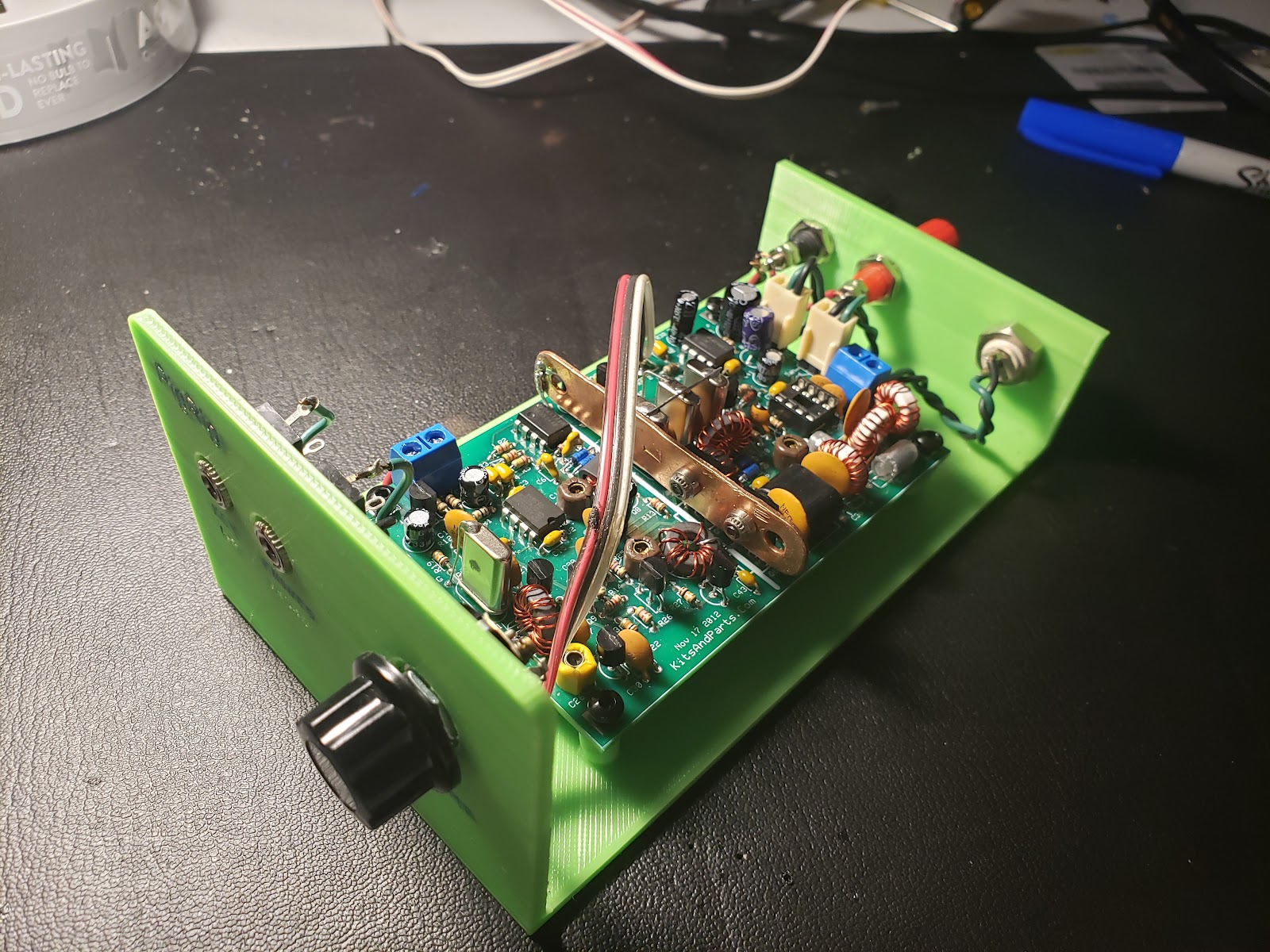
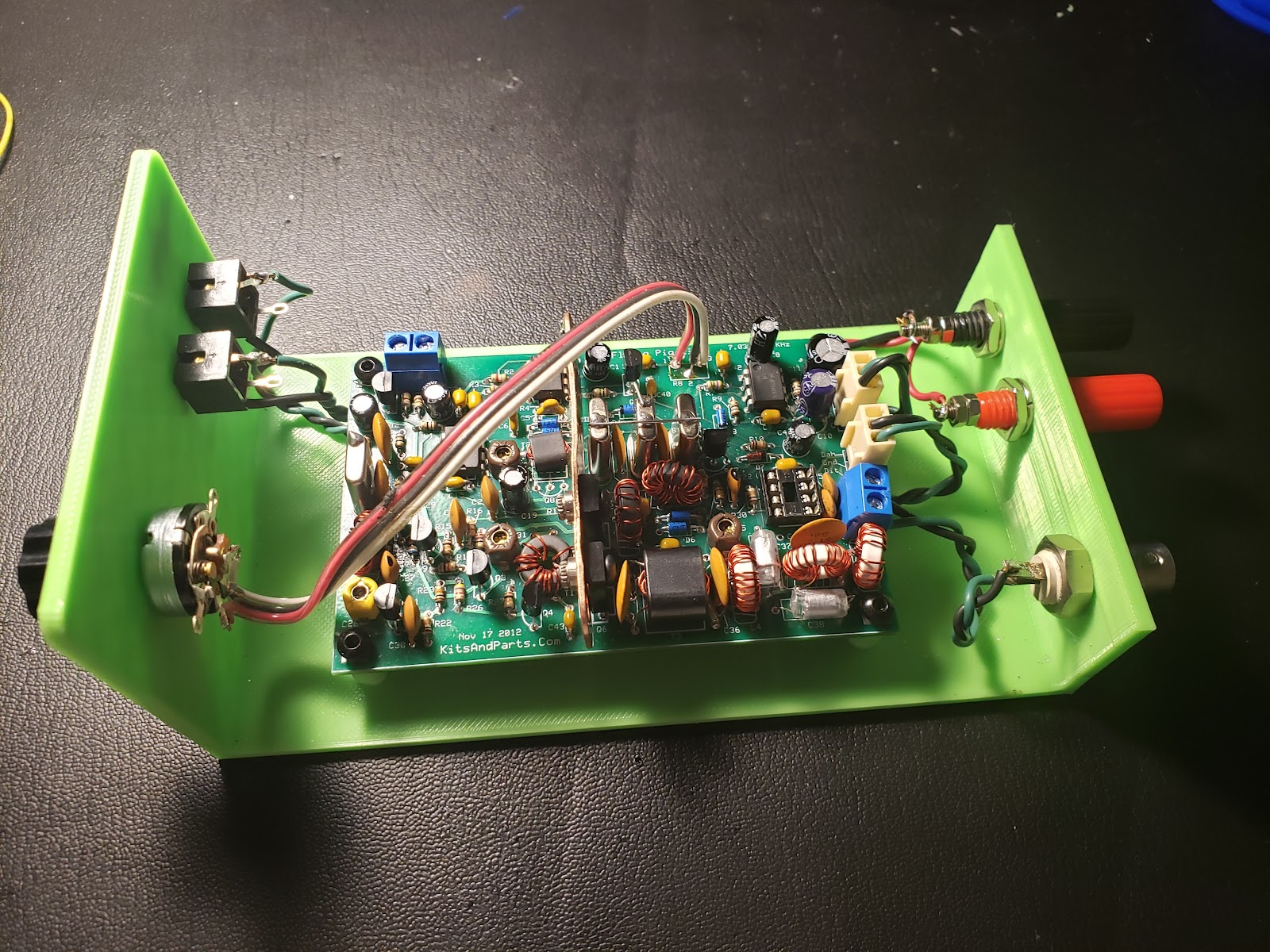
 The photo below shows the setup to test using the Tuna Tin S with the 10W linear amp. Click to enlarge.


  • The Tuna Tin S is on the left in its green case. It is supplied from a 5V wall wart via a USB micro connector to the Wemos D1 Mini, which supplies regulated 3.3V to the other components in the unit: 1) encoder, 2) display and 3) Si5153 breakout board.  Channel 1 of the oscope is connected to the RF output of the unit. 
  • The RF output of Tuna Tin S is wired to a DC blocking capacitor over to the input of the 10W amp. The amp is supplied with 12VDC from a lab power supply.  A test lead is used to ground the enable control line of the amp to turn it on for testing. 
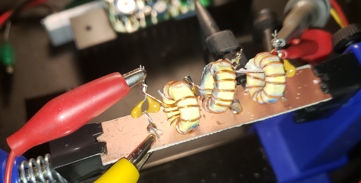
  • The output of the RF amp is routed to the 40m low pass filter, seen built on the end of a copper clad PCB.  The output of the 40m low pass filter is routed to a dummy load seen on the extreme right of the photo.  Channel 2 of the oscope is connected across the dummy load. 
The test results are shown below, click to enlarge

The input is about 3 Vpp, and is a square wave. There is excessive ringing.   The ringing may be coming from the scope probe, but could also be due to the lack of a resistive termination at the input of the amp. 

The output is 80.8 Vpp,  across a 50 ohm load, which works out to 16.7W  (42.2 dBm) of power.  Previously I tested the amp with a sine input and found I needed a 5Vpp input to drive the amp to 10W output.  I'm assuming for now that the square wave input is driving the amplifier harder, generating an unexpected high amount of power. 

I plan to refine the system by adding an attenuator at the input of the amp to suppress the ringing and lower the input to drive the amp output to 10W.  The RF appears to be getting into my power supply;  the current and voltage meters get erratic when the amp is enabled.  This needs to be fixed.  I'll need to order some chokes and a common mode a filter on the power leads.   I also plan to do an FFT on the output waveform to assess the suppression of harmonics. 

Monday, January 16, 2023

QRP Labs 10W PA (4) -- Designing 20m LC Low Pass Filter

 The circuit for the 20 meter filter for the QRP Labs 10W PA is a scaled version of the 7th order Chebyshev filter for 40 meters, using the same filter table. The component values are given in the schematic.


I do not have 150p NPO capacitors in my stock, So I used 100 pF in parallel with 47 pF.  I used T50-6 cores for the inductors, again with total 300 mW predicted wire and core losses. The LTSPICE predicted filter response is below.

The filter was assembled on a strip of single sided PCB, as shown in the photo below. Click to enlarge.

The full power filter output into a dummy load is shown below.  Click to enlarge. The input voltage is approximately 3.5 Vpp. Frequency is 14.0000 MHz.  Output power is 9.9W.  Gain is about 25 dB.


Sunday, January 15, 2023

QRP Labs 10W PA (3) -- Designing 40m LC Low Pass Filter (Updated)

 To design the 40 m LC filter for the 10W amp output,  I decided to use the 7 pole Chebyshev table found on Page 6-43 of the 1981 ARRL Handbook.  Click the diagram to enlarge.  

The information can also be found in the 1979 QST article "Low-Pass Filters for Amateur Radio Transmitters", by E. E. Wetherhold, W3NQN.  The design for 40 meters supposedly uses standard capacitor values for C1, C3, C5 and C7, but I don't have any 300 pF caps in my parts collection, so I'll use 82 pF plus 220 pF to get close. I have T50-6 cores in my parts store, so I'll them.  The table of parts is: 
  • C1 & C7 -- 300 pF NPO, approximate with 82 pF in parallel with 220 pF
  • C3 & C5 -- 680 pF NPO
  • L2 & L6 -- 1.37 uH, 18T on T50-6 core, using 26 AWG enamel wire
  • L4  -- 1.62 uH,  20T on T50-6 core, using 26 AWG enamel wire
The figure below shows the LTSPICE circuit for simulation (click to enlarge). The AC voltage source is set up with a source impedance of 50 ohm. 

The response of the filter is shown in the plot below (click to enlarge).  The attenuation at the 14 MHz, the lowest possible 2nd harmonic is -40.5 dB.

At the fundamental frequency of 7 MHz, with 10W power at the load, the current through the inductors will be: 

$I_L=\sqrt{10W/50\Omega}= 447 mA$

Using the micrometals.com design page the losses in the core and wiring are predicted to be 100 mW for each core.  This will generate a minor and tolerable 300 mW of loss in the filter. 
 
Some useful LC filter links: 

Saturday, January 14, 2023

QRP LABS 10W PA (2) -- Successful Test

The previous post about he 10W Amp is at: QRP Labs 10W Linear Amp (1)

Mike, KA5VZE, assembled the 10W amplifier and delivered it to me, the other brother, KG5KCW, yesterday.  After carefully setting the idle current in the finals to 125 mA per transistor, I drove the amp with a signal generator into a dummy load.  The amp seems to work as promised.  I only tested at 7030 kHz.  

Measurements: 

Input voltage: 3.48Vpp

Output voltage: 64Vpp

Voltage gain: 18.4 V/V,  or 25.3 dB (kit gain spec is 26 dB)

Next step is to design and build low pass LC filters for 40 and 20 meters.

We may also need a booster for the frequency synthesizer circuit we'll use to drive the amp with. 

The test setup is shown below.  Outside the picture is a 25W 50 ohm dummy load.


Photo below shows the signal generator setup.   The generator is set at 4.2V but the voltage at the input to the amp is 3.48V,  this calculates to an amp input impedance of 244 ohm.

Photo below shows the test results on the oscilloscope.  The calculated gain is given above.  The output power is 10.4W.  The input current to the amp is 2.36A @ 12V,  input power is 28W and efficiency is 37%. 


Thursday, January 12, 2023

Flying Pig Rig (9) -- Trying to make a QSO

I don't have an antenna, so I used a fishing rod to throw some line over the house and used that to drag a random wire.  Borrowing from KA5VZE, I put an 9:1 "un-un" at the feedpoint and used a 4-State QRP tuner to match to the random wire.  The match seems to work fairly well.  

Here's a photo of my setup.  Click on the photo for full size: 


The "Morris" key is on the right,  PigRig is center, and QRP tuner on the left. 

I was frustrated for a while because there was no offset from transmit to receive.  If someone transmitted on the  PigRig frequency of 7030.7 kHz,  the tone was so low it was difficult to discern.  I followed the discussion in the PigRig instructions and substituted a 15 pF capacitor for the 12 pF cap in the oscillator offset circuit.  This didn't help.  Probing around in the circuit I found that the offset suddenly started working.  There was a cold solder joint in the circuit.  I fixed that, and now, with TX adjusted for 7030.69 kHz, the RX frequency is 7031.20 kHz,  so the offset is about 500 Hz.  That should work well.  

I have been CQ a couple of night now, but no QSO's yet. 

Monday, January 2, 2023

Flying Pig Rig (8): Installed in box, ready to test on-air

I 3D printed a cabinet for the Flying PigRig and installed the board and controls and input/outputs. 
When I installed the inserts in the stanoffs, the inserts swelled the standoffs and the inserted got clogged with melted plastics.  It's good enough for now, but maybe later I'll print out another cabinet.  I put in letters on the front and back for control labels, but those didn't work out.  The 2mm letters didn't have enough definition to read well.  Also, the plastic is porous and wicks up any ink or paint, smudging the label in an unsatisfactory way.

At 13.6 volts, the rig outputs about 4 watts of power.  The offset between transmit and receive frequencies is not wide enough, resulting in very low frequency on the received signal at 7030.7 kHz. 

I'll test the rig on an antenna later to see if I can make a QSO.