I'm in the process of building an SWR meter. The directional coupler is the "tandem type as shown below.
This is a very simple circuit that is fairly easy to build. It consists of two current transformers TR1 and TR2. Each transformer has a 1 turn "current" side and N turn "voltage" side. In my case I chose to use FT50-61 cores with 20 turns on the voltage side. These cores have an AL of 69 uH per N^2/1000, where N is the number of turns. This turns out to be 27.6 uH on the voltage side and 0.069 uH on the current side.
I simulated the the coupler using LTSPICE as shown below, click to enlarge:
Note that I've used parameter Lx to be able to change the inductance of the voltage side of the transformers. I did this in order to determine minimum inductance needed for the coupler to work at a given low frequency. For the current side of the transformers, the inductance is Lx/400, since the turns ratio is 20:1. I measured the self resonant frequency of the transformer and added 10 pF of stray capacitance across the windings (C1 and C2)
Upon simulation this circuit, using 22 uH on the transformers:
The excitation voltage V1 is 1 volt.
As shown, the load is perfectly matched and Vr should be zero.
Upon simulation:
The voltage Vf = 49.875 mV. It should be Vin /20 = 50 mV
The voltage Vout 997.5 mV
The response is flat from 1 MHz to 100 MHz for a matched load.
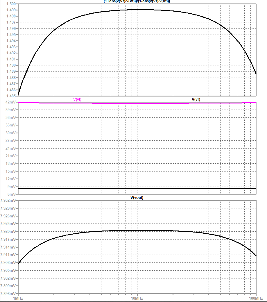
If I change to a mismatched load of 75 ohms, the frequency response is affected. In the plot below (click to enlarge), the load voltage is plotted at bottom, measured forward and reflected voltages in the center plot, and measured VSWR in the top plot. The nominal sensed forward voltage should be 50 mV, but is measured as ~42 mV, Vr should be 10 mV but is measured at 9 mV
VSWR should be 1.5, and at 10 MHz is measured at 1.499. Additionally the accuracy of the VWSR measurement falls off at low and high frequencies.
Changing the load to 150 ohms, the simulated response is shown below.
Nominal load voltage 1V, simulated 0.998V
Nominal Vf: 50 mV, simulated 32.5 mV
Nominal Vr: 25 mV, simulated 17 mV
Nominal VSWR: 3.0, simulated 2.99