Wednesday, June 28, 2023

3D printing: Garage wall bracket

 I am getting pretty familiar with Fusion 360 now...  it's pretty simple....   sketch then extrude, sketch then extrude, sketch then extrude....

I needed a simple bracket to hold a digging bar against my garage wall for starage and threw a model together in about 20 minutes. See Fusion 360 screen shot below:


A quick drawing is shown below to indicate size. The bracket is 3" wide:


Tuesday, June 20, 2023

SWR Meter (14) - Box rear panel for SWR coupler

 I am modifying the rear panel of the 3D box to accomodate the shielded SWR directional coupler. The back panel is being modified into a box that holds the two sides of the coupler.

Rear view of modified panel:


Front view of modified panel: 

click to enlarge


Front view with cover removed, showing the two coupler compartments: 

click to enlarge

The lower compartment will have UHF connector inputs and outputs from the rear.  The upper compartment will have forward and reverse outputs, either through twisted pair connections are through SMA connectors. 

Developing....

SWR Meter (13) - 3D printed box parameterization fixed

 I started over with the parameterization of the box.  After watching a Youtube video on parameterizing hole patterns, I was able to figure out how to get the hole patterns to work correctly with the parameters.   3"W by 5"L by 2" H box is shown below.   The hole pattern algorithm needs a starting offset distance from the edge of the panel to the first hole for each direction W, H, and L.  Then an equation determines the number of holes and the interval in between:


The paramters for this box are shown below.   

  • boxH, boxL, boxW:  parameters are the box outer dimensions
  • thick1, thick2:  parameters are panel thickness parameters
  • ??hole: parameters are for the screw holes,  clearance and tap
  • offset?:  parameters are the offset distances to the first hole for H, W, and L
  • nscr?:  parameters are the equations to determine the number of holes and interval between holes.

click to enlarge

Here is the same box with the length set to 3 inches.  Notice the number of holes along the length has been reduce from 5 holes to 3 holes

click to enlarge


Thursday, June 15, 2023

SWR Meter (12) - 3D printed box parameterization problems.

Using Fusion 360, I have attempted to parameterize the design of the RF tight project box that I designed for the SWR meter.  The parameters I've used are: 

  • width, length and height of the box
  • thickness of the panels
  • countersunk clearance hole parameters
  • self tapping screw pilot hole paramters
  • L: length of the box
  • H: height of the box
  • W: width of the box
It takes some experience to find the most efficient way of implementing the paramters.  The challenge right now for me is to get the screw locations to automatically adjust to the changes in the box dimensions and panel thickness. 

The photo below shows the SWR box after changing the box height from 1.5" to 2".  Note the row of screw holes on the side of the box is now in the wrong place.  So the challenge is to set up an equation to parameterize the screw hole locations.   

Developing....


click to enlarge

Wednesday, June 14, 2023

SWR Meter (11): Sheet metal box progress

 Continuing frorm SWR Meter (9)   we have built the first prototype of a sheet metal box for the SWR meter.  The box is made from 22 ga weldable steel for the bottom and 26 ga weldable steel for the top. Note that the holes have been drill for attaching the top to the bottom, The row of holes along the top are for fastening the top to the internal dividers. The inside dimension of the top is about 1 mm too wide.  That's not bad but we still need to work on making predictable bends. 

click to enlarge

The photo below shows the interior of the box, with a 3D printer divider (green plastic) mounted to the botoom.   

click to enlarge


Monday, June 12, 2023

SWR Meter (10) - 3D printed project box design in Fusion 360

 I tried another SWR project box design using 3D printing rather than a sheet metal box.  The design philosophy is as follows: 

  • Use flat panels as the box components, no U shapes or L shapes.
  • Use 0.113" (3mm) panels
  • Use countersunk #2-28 self tapping screws to assemble the panels together.
  • Use enough screws spaced close together to ensure no open cracks along the seams where the panels join.
  • All inside surfaces should be flat to facilitate laying copper or aluminum tape on the inside surfaces. 
  • Copper tape on the inside surfaces should form a continous conductive surface inside the box to be RF tight.

The resulting box is show below, it is 3" wide, 1.5" high, and 5" deep.

click to enlarge
You can see the places where the #2 countersunk screws are used.   there are quite a few of them. 

The drawing below shows the box exploded into two sub assemblies of 3 components each.  

click to enlarge

After 3D printing the resulting box is shown in the photo below. 

click to enlarge

The box has a few problems: 
  • There are a LOT of screws.  I only installed every other screw.
  • The Torx drive on the #2 screws doesn't really drive the screws well. The driver slips out of the screw head often.
  • Driving the self tapping screws into the edges of the 3 mm thick panels tends to cause the panel surface to dimple.
Even with problems above the box will probably be practically useful.   Next I will work to fit the SWR meter parts into the box. See the photo below.  I will need to add a couple of divider shields. From left to right, the SWR coupler will be installed on the back wall of the box. The logarithmic detector PCB will be mounted on the floor of the box, which the OLED display and the ATTiny85 controller will be mounted on the front of the box. 

click to enlarge


Wednesday, May 24, 2023

Philmore 12V Power Supply (6): PS123 in the box unit from ebay.com

I purchased a Philmore PS123 from ebay.com for \$10.  The unit was still in the box with original one-page flyer that passes as the operator's manual. The unit's schematic was shown, but doesn't quite match the wiring in the cabinet.   It's almost identical to the circuit I traced out and previously blogged about.  The filter capacitor is 2200 uF, rather than 2000 uF as shown in the schematic. The schematic shows a single 1K resistor from the collector of TR1 to the anode of the zener diode.  The actual circuit has a 5.6K resistor from the collector of TR1 to the negative side of the 500 uF capacitor, then a second 5.6K resistor from the negative side of the 500uF capacitor to anode of the zener diode.


click to enlarge


The reverse engineered circuit is shown below.  

click to enlarge

A photo of the PS123 is shown below. 

click to enlarge


A photo of the interior of the unit is shown below. Note there appears to be a splice in the line going from the diode bridge to the fuse. 

The performance curves of load regulation and ripple vs. load are given in the included flyer. 

click to enlarge


Monday, May 22, 2023

Sheet Metal Inventory and Gauge Table

 I bought two sheet metal squares at Lowe's  today.  I made a mistake and bought a second sheet of 26 Ga, when I intended to buy 22 Ga. 

12" X 18", 26 Ga, Zinc plated steel
12" X 18", 26 Ga, Weldable steel


SWR Meter (9) - Project box design in Fusion 360

 This is my first cut at the SWR project box design.  I used the sheet metal options in Fusion 360 to design a two piece sheet metal box with dividers. The box is 3" wide by 4.5" deep.

click to enlarge


 The division of the box into shielded compartments can be seen with the top removed.  Four pieces are cut from 0.8 mm aluminum: 1) the base, 2) the top, and 3) the dividers.

click to enlarge


The sheet cutout patter for the base is shown below. Dimensions in mm.

click to enlarge


Cutout pattern for the top are shown below.  Dimensions are in mm. 

click to enlarge


Cutout pattern for the basic divider is given below, later versions may need a separate version for each divider.  Dimensions are in mm. 

click to enlarge


CARDBOX CHASSIS AND CABINET BUILD


Friday, May 19, 2023

SWR Meter (8) - Project box

 I am going to make the SWR meter enclosure out of sheet metal, and do the drafting in Fusion 360.

The plan for the enclosure is shown below: There needs to be a conducting shield between the tandem coupler and the log amp board.  I'll use bulkhead mounted SMA connectors to feed the RF signals.   I'll also put a shield between the detector board and the MCU/Display section.  A 9V battery will go in the MCU section.  Front panel controls will be a small battery switch, and a cutout for the OLED display.


Wednesday, May 17, 2023

Philmore 12V Power Supply (5): Counterfeit regulators from China!

I completed the final wiring of the new controller board and tested it out on the bench.  It ran well with no load so I mounted the the board and the LM338 regulator into the cabinet. The photo below shows the control board connected to the LM338 on the left.  It was being driven at 18V by my bench supply, and produced 13.8V output with no load. 

click to enlarge

I wanted to be able to operate at 13.8V @ 2 amps continuously.  For testing I bought a 15 ohm 10W resistor and two 4 ohm 20W resistors which I put in series to make an 8 ohm 20W resistor.  The resulting currents at 13.8V should be 0.92A  and 1.73A respectively.  

After I installed the LM338 and the board in the cabinet and connected the output of the rectifier, it again ran well with no load.  The transformer is a nominal 18VAC secondary, as marked on the transformer itself.  This should give a peak voltage under no load of 25.4VDC on the filter capacitors at no load.  The actual measured voltage was more like 28V however, so the house line voltage is probably a little higher than nominal.  I loaded the supply with the 15 ohm resistor and got 13.5V @ 0.9A.  The input voltage dropped to 24.6V.    When I tried the 8 ohm resistor however, the LM338 died.  I checked my schematic and discovered that I'd wired a protection diode wrong, I assumed this was the reason the LM338 died. 

I corrected the protection diode mistake and replaced the LM338, and began further testing.  Again the unit worked well with the 15 ohm load, and again the 8 ohm load killed the LM338.   I made some measurement between terminals of the LM338, both on a good unit, and on a blown unit.  It appears that the voltage input terminal had opened up in both blown units.  I suspected that the bond wires from the LM338 input pin to the die had fused open. 

I did various test, and destroyed five LM338s in total.   Below is a scope photo of a failure.  In this event the supply is connected to an 8 ohm resistor.  The supply is cycled on, and the voltages at the LM338 are monitored.  The yellow trace is the input voltage.  You can see the voltage step from zero and increase to a steady state as it charges the 9900 uF filter capacitor. You can also see ripple peaks from individual rectified AC peaks. The blue trace is the output voltage of the LM338.  The output voltage rises with the input charging. Once the input voltage gets above the set voltage plus the dropout voltage, then the output voltage settles at 13.8 volts or so.  The cyan trace shows the Adjust pin of the LM338. When functioning properly, this voltage should be 1.25V lower than the 13.8 volts, which appears to be the case. 

But note that about 150 ms after the supply turns on the output drops to 0V.  This must be the instant when the bond wire inside the LM338 burns itself open.  The Adjust pin voltage is tied to the output through a voltage divider, so it falls to 0V too.   Once the output current disappears, the input voltage is no longer loaded, and the input voltage soars from about loaded 23.5V to unloaded 27V or so.  

click to enlarge
Doing some investigations on the web, I discovered that counterfeit LM338s are very common, and that is apparently what I've purchased.    Real LM338s should be able pass 5A continuously, and up to 12A transiently. This is apparently lower current unit (maybe an 3A LM317) that has insufficient bonding between the die and the pins. 

At any rate, I will not be able to use the LM338s that I bought and will have to probably redesign the board.   Very disappointing!


Saturday, May 13, 2023

Philmore 12V Power Supply (4): Adding adapter bracket

 I have designed and 3D printed an adapter bracket that will hold a circuit board in place inside the Philmore PS123 power supply.  The circuit board will be a hand assembled version of the LM338 control circuit mentioned earlier. (LINK)

The Fusion 360 bracket model is shown below.   The bracket sits on the bottom of the cabinet. The small holes align with the circuit board mounting holes for the original control circuit board.  The large holes are to clear the screws that mount rubber feet underneath the cabinet. The circuit board is 80 mm wide and 60 mm high. The 80 mm side slides into the slot with components extending into the inside of the cabinet. 
click to enlarge

A photo of the bracket installed in the cabinet, adjacent to partially populated circuit board is shown below. 
click to enlarge


Below photo shows the circuit board as it will be installed.  Terminals blocks on the edge of the board are, from left to right, LM338 connections, power in from rectifier, power out to binding posts. 

click to enlarge


I'll get the rest of the components mounted on the board and wired up tomorrow.  Maybe even start testing. 


Saturday, May 6, 2023

SWR Meter (7): Test results of log amp detector

 I ran tests on the response of the SWR detector PCB.  Everything appears to function well. The response graph is shown below

click to enlarge

It looks like I've got the noise problems worked out.  The response is very close to what is given in the data sheet.  There is a jog in the response at about -50 dBm.  This jog is there because I had to switch to an attenuator to get signals down below -50 dBm.  The attenuator changes the load on the signal generator slightly, resulting in the slight offset in response below -50 dBm.

click to enlarge

I am designing the circuit to measure power up to 300W.  The amplitude of the Vr port on the coupler is: 

$V_R=\frac{\sqrt{PR}}{N}$

where: 
  • P is the power on the load
  • R is the load resistance (50 ohm)
  • N is the number of turns on the current transformer of the coupler. (20)
This gives an RMS voltage of 6.1 volts for VR for 300W on the load. 

The AD8307 datasheet define dBm as:

$dBm =10\log_{10}\left( \frac{V_{RMS}^2}{R}\cdot 1000 \right)  $

Using this formula,  6.1 volts is 28.7 dBm.   In order to keep the dBm input to the AD8307 to under 10 dBm,  I will add a 20 dB attenuator between the coupler and the AD8307.


Monday, May 1, 2023

40 meter NE602 DC RX -- 2023 version

 At the request of KA5VZE, AKA "my big brother", I am going to make a replica of my original 1987 "NE602 40 meter RX".   I covered the back story for my 1987 version in the immediately preceding blog post

I have transferred the original design into a KiCad project and produced a new PCB layout on the same size 1.5" by 2" board. The details are shown below.  I will order the boards from PCBWAY this week.

The original schematic is shown below.  Except for the trimmer capacitors, all parts can still be obtained for the RX.  (I guess from 1987 to 2023 makes the original project 35 years ago.  Where did the time go?) 

click to enlarge

For the 2023 version, I've added connectors to facilitate working with the board for testing and mounting in the cabinet.   The new schematic, entered into KiCad is shown below: 

click to enlarge.

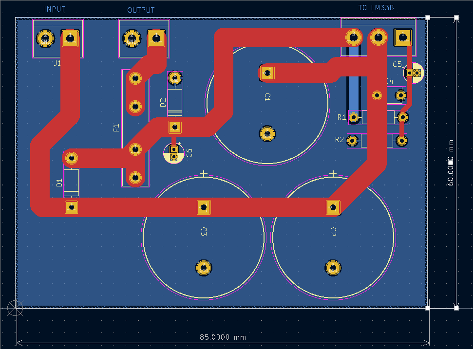
The layout for the PCB, shown below is done on a two sided board, with the bottom side serving as the ground plane. The ground plane is cleared out underneath the oscillator circuit in the lower left and under the tuned antenna circuit in the upper left. 

click to enlarge


The KiCad generated 3D view is shown below, with my added annotation.  

click to enlarge

Compare this to the original layout from the 1987 version and you can see both PCBs are similar. 

click to enlarge


40 meter DC NE602 RX (2): Background

Link to first post about 40m NE602 DC RX 

The original 40m DC RX was built to evaluate the NE602 mixer circuit. This was 1987 and I received a free sample of the NE602 on a blister card.  It looked very useful, because it had the oscillator and double balance mixer all in one chip.  I quickly learned that NE602 overloaded very easily but I still built a receiver up just for fun. draft article submission from 1987

Here's a photo of the original 1987 NE602 RX.  It was housed in a Radio Shack cabinet, using a vernier dial for tuning,  and volume and phone connections on the front panel.  The 9V battery was inside the cabinet, and the antenna connection was through an RCA phono connector through the back panel.


Below is a photo of the interior of the RX.  Click to enlarge.


The original circuit board was single sided, as shown below in a view from the component side.  Click to enlarge. 


Friday, April 28, 2023

SWR Meter (6): PCB populated, ready for testing.

 I have populated the SWR detector  PCB. The 0603 capacitors and resistors are about the size of sesame seeds and require a lot of care to install.  With a little practice it seemed I was able to solder them to the board fairly well. 

I set out a white paper napkin to hold the parts before soldering.  The white napkin has good contrast with the tiny parts so they are easier to see and handle. I used a small Ungar Princess soldering iron with a very sharp point.  I pair of tweezer is necessary to pickup and position the parts. I used ultrafine 0.3 mm diameter solder. To solder a 0603 part on the board, first solder a small dab of solder on one of the pads. Pick up the part with the tweezers and place it in position, one end on top of pad with the small dab of solder, the other end of the parts goes on the other unsoldered pad.  Heat the soldered pad until the solder melts, then continue until the part itself heats up and wets with solder. The part will self-center on the soldered pad. After letting the pad cool. Solder the other pad to the part. 

click photo to enlarge

I tested the voltage regulator on the board. It produced 5V whenever the input voltage exceeded 6.5 volts. 


Tomorrow I'll start testing the rest of the board.

Philmore 12V Power Supply (3): LM338 controller circuit and PCB

 Until I get some more information to restore the Philmore PS123 power supply, I'm going to install a modern controller circuit in it and use it on my bench. The circuit is shown below.  


I got the input filter capacitors at Affiliated Electronics in Tulsa.  The combined capacitance is 9900 uF, which might cause some current inrush problems.  My measurements on the winding resistance of the transformer indicates the inrush currents will be about 30 amps on the secondary, and 5 amps on the primary mains circuit. D1 and D2 are transient protection for the LM338. The LM338 controls for a 1.25 volt reference voltage from Vo to the ADJ terminal.   The R1-R2 voltage divider is designed so that when the 1.25 volts appears (across R1)  the voltage across R1-R2 in series (the output voltage) will be 12 volts.  This is a straightforward circuit and is close to what is recommended in the LM338 datasheet. 

I moved the fuse from the cabinet mounted holder onto the PC board.  This will be me more room in the cabinet.  I plan to also add an 3 conductor AC cord to ground the chassis, and also add an inline mains fuse. 

The PCB layout is shown below.  Red is front, blue is back side. All external connections are taken out on screw terminals.  This will allow me to change out the controller without any trouble if I want to experiments with other control types. 


The 3D view of the board is shown below. I will 3D print a plastic bracket to go on the floor of the chassis and hold the PCB vertically with the screw terminals along the top.


Thursday, April 27, 2023

Philmore 12V Power Supply (2): description of unit as found

 I continue to work on the Philmore 12V Power Supply.  Below is a photo of the inside of the unit.  I've indicated where the diode bridge is connected directly to the output positive binding post of the unit. You can see the mounting location of the TO-3 pass transistor on the back of the chassis behind the transformer. A small circuit board, not shown, mounts on the floor of the chassis to the left of the transformer. 


The top and bottom view of the control PCB are shown below. 

There appear to be several uninstalled components on the board, these were probably components for some sort of short circuit protection.

I found a YouTube video of a bench repair of a PS123, replacing the pass transistor. 
https://youtu.be/5IpG66imsn8

SWR Meter (5): PCB arrives from PCBWAY!

 The circuit boards for the SWR project came in. Click to enlarge. 


I will start work populating the board tonight.