Saturday, March 30, 2024

Duracraft VS-312 Bandsaw restoration (7): operational test of new 3D printed gear

I modified the Fusion 3D model of the motor gear from 10.15mm ID to 10.12mm ID.  I used PLA material for the gear, 100% fill. It took 2 hours to fabricate.

To mount the gear onto the motor shaft, I first used the old gear to find the best position of the gear on the shaft. If the gear is too far up the motor shaft, the belt will wander off the wheel,  if the gear is too far down the motor shaft, the belt will get frayed on its outer edge by the outer lip of the gear.  When I found the optimal placement of the gear, I marked a short stick with a pencil to mark the height of the top of the gear from the saw case. 


To install the new gear, I first boiled some water in a tea kettle, poured it into a disposable cup, then dropped the new part into the hot water to let it expand.  After a few minutes I took the hot gear and tapped in down on to the motor shaft until it lined up with the mark for the proper height.  I had no trouble moving the gear down the motor shaft, it went down with just light tapping with a wooden mallet.


The saw was very finicky to get set up.  The three tension controls interact quite a bit.  After about an hour of getting familiar, I finally got the saw running.  I adjusted the blade position so that the blade saw teeth were slightly off the tires: 

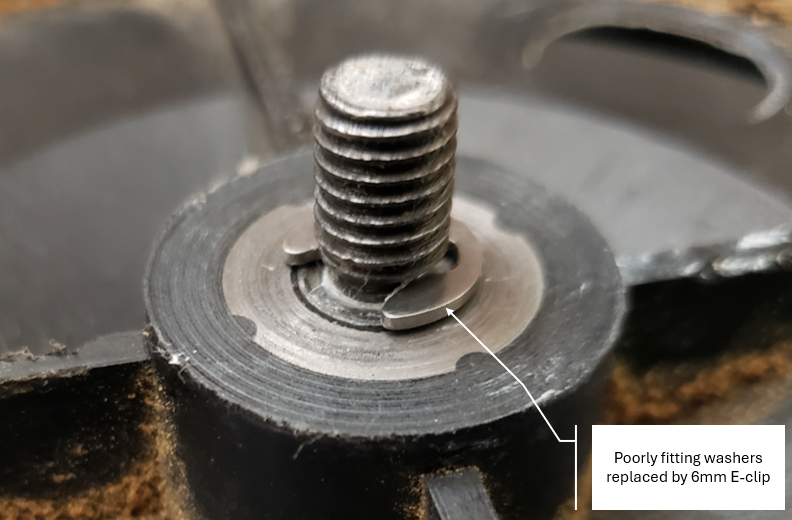
The lower and upper blade guides are definitely worn out,  I'll cover rebuilding the guides later. 

Below is a video of a test cut with the saw:


Duracraft VS-312 Bandsaw restoration (6): wheel alignment study

 I have taken some time to better study the wheel alignment on the Duracraft VS-312 bandsaw. 

The wheel axles are in 10mm bearings with the wheels nominally 1 inch wide (25.4mm).  The axle pins screw directly into the bandsaw casings. 

The left photo below shows the mounting hole in the saw casing, and on the right is a photo of the axle pin partially screwed in.

click to enlarge


The photo below shows an axle pin

click to enlarge


Below is a diagram of the axle pin, showing dimensions: 

click to enlarge

Going from the wheel hub (left side) to the case (right side) are the following sections of the pin:

  1. A slotted screw head
  2. A snap ring the holds the outer wheel bearing
  3. A shoulder to the bearing formed by a 6 mm OD 1mm wide recess
  4. M8 screw threads that screw into the bandsaw casing.
The photo below shows the axle pin installed through a wheel bearing.  The wheel bearing is about 1mm narrower than the bearing area on the pin, as is noted in the photo. This results in 1mm on axial play in the bearing, which I reduced by putting a total of 0.7mm of shim washers between the snap ring and the outer side of the wheel bearing.

click to enlarge

As I originally found the bandsaw, it had two 5/16" washers installed between the saw casing and the pin's bearing shoulder as shown in the photo below.  The washers had a large ID, giving a loose fit around the threads. Also, because of the 6mm slot next to the shoulder, the washers seated poorly when installed. The washers move the wheels outward away from the case by 3mm, which caused the gear wheel of the motor to be far out on the end of the motor axle.

click to enlarge

I ordered a metric E-clip assortment and replaced the poorly fitting washers with a 6 mm E-clip.  I am convinced that this was the way the axles were originally designed to be configured.  The E-clip fits in the slot in the pin and seats well. The distance between the inner side of the wheel and the shoulder on the pin is now reduced to 1mm, moving the drive gear on the motor inwards by 2mm. 

click to enlarge


Another problem I found was that the upper wheel didn't have any washers installed. This results in a 3mm misalignment of the upper wheel in relation to the lower wheels. As designed, the upper wheel has fixed alignment with the other two wheels, but has an adjustment of angular alignment to position the saw blade.  So the 3mm misalignment was likely causing binding when the blade turns.  I have now installed the proper E-clip in all three wheels and I think I should get good alignment of the three wheels with much less friction than before. 


Friday, March 29, 2024

CARI Chess & Amateur Radio Int'l

 I have 2 qsl cards from Tom Palmer whom my dad and I


played chess with.  It shows the Chess Frequency Schedule at the time (1984).  I had the game in my log which disappeared long ago.  I sure would like to play "on air" again.  So all you Hamster out there that love chess give me a call.  my email address is on my QRZ page under KA5VZE.  The same call as my novice call.  I still write down everything that is said to me and may even record.  I only do cw but if someone will teach me to tune up my FT 757- GX for fon I would gladly oblige them.

Try this link also: https://www.kb6nu.com/play-chess-cw

73s Mike Morris KA5VZE


Monday, March 25, 2024

12V 7.2AH SLA battery (3): XL4015 buck converter charger

 I ordered step down modules from Amazon.  I bought 3 modules for $11.37 total.  The modules are rated for 5A with outputs from 0.8V to 30V. I haven't measured the dropout voltage but it appears to be slightly more than 1 volt. 


The unit has a voltage regulation adjustment and a current limit function.  I set the voltage at 13.8V and set the current limit to 0.72A, which is 10% of the battery's 7.2 Ah capacity.  After discharging the battery to about 50% state of charge (SOC) I recorded the current and voltage of the battery as it was charging.  See plot below: 
click to enlarge

The current is limited at 0.70A for the first hour or so. Then the current drops exponentially while the voltage approaches a constant voltage of 13.5 volts or so.   This is controlled 2 stage charging.  For a third stage the voltage could be dropped slightly for long term trickle charge.  This seems like a pretty good charger circuit and costs less and $4 for each module. 


Saturday, March 23, 2024

12V 7.2AH SLA battery (2): 1st current limiter

 My initial try at a current limiter is a foldback circuit I used back in the '80s for charging a small battery. See below.  The charging current flows from Vin through Q2 collector to emitter, then through current sensing resistor R2.  When the voltage across R2 reaches about 0.65 volts, then Q1 turns on and robs the base of Q2 of current, limiting the current to 0.65V/R2, in this case the current limit is 0.79A. 


As built the circuit is shown below.  It functioned as predicted, limiting the battery charging current to about 0.78A.  However my lab power supply only goes to 18V and this circuit required 3 or 4 volts to operate properly.  But the real problem was that it was difficult to predict the final charge voltage once the battery current fell off.  This gives a risk of undercharging or overcharging the battery.  I will try a different approach with a LM317 regulator IC.


Friday, March 22, 2024

12V 7.2AH SLA battery (1)

 I bought a 12V, 7.2AH sealed lead acid (SLA) battery from Amazon (link). 


As a reference for the required charging curve I'm using the chart from page 7.38 of the 2023 ARRL Handbook.  See graph below.  For Stage 1 current I use C/10,   for 0.72 A.  Topping charge voltage will be the bottom of the Handbook guide of 2.3V to 2.45V per cell, i.e., 13.8V.  This is in accordance with voltage recommendations on the side of the battery. Float voltage will be 13.5V.  So summarizing: 
  • Stage 1: constant current 0.72A
  • Stage 2: constant voltage 13.8V
  • Stage 3: constant voltage  13.5 V
I am in the process of designing the charging circuit now.  I have ordered some UC3906 Lead Acid charger controller ICs from Amazon (link).  I've also ordered XL4015 based buck converters (Amazon link). These buck converters can be programmed for an output voltage and current limit that will produce multi-stage charging. I'm also thinking of using a LT3652 IC based module (Amazon link)


Duracraft VS-312 Bandsaw restoration (5): final testing fail

 Yesterday I installed the upper and lower blade guides, then mounted the table and did some tests.

  1. The blade guides are worn and need to be rebuilt.  I'm hold off on discussing the blade guides until I start doing their rebuilds. 
  2. The table wasn't hard to install.  
  3. When I tested the saw on random blocks of soft wood, it didn't cut well.  I wonder if I've got the wrong style of saw blade. 
  4. After several minutes of testing the drive wheel started slipping, then stopped working all the way.
  5. I will have to 3D print out a replacement with a smaller size hole and try it again.  I may work on some scheme to add a allen screw locking mechanism.  If I do, hopefully the PLA plastic isn't too soft.


Wednesday, March 20, 2024

Duracraft VS-312 Bandsaw restoration (4): Drive sprocket and belt installed

I did the following work on the Duracraft bandsaw today:
  1. Installed washer shims on the axles of the wheels.  Each pulley required about 0.6 mm of shimming to reduce the side play on of the each wheel on its axle. 
  2. I used silicon grease on each axle to reduce friction and noise.  
  3. I installed urethane bandsaw tires on the wheels.  Not that easy, easier with practice. 
  4. I installed the 56-7/8",    3/8" wide, 6 tpi saw blade.  
  5. I adjusted the tension and blade position using the tension adjustment and camber adjustments on the top wheel.
I ran the saw for about 10 minutes and don't see any problems as yet. 
Now forward to get the blade guides installed. 
Photo of the saw in its current state is below. 


Sunday, March 17, 2024

Duracraft VS-312 Bandsaw restoration (3): Drive sprocket and belt installed

 On the Duracraft bandsaw... after checking the alignment of the wheels, I've found that the wheel bearing have about 1mm of side to side play.  I've ordered shim washers that I'm going to use to get the play down to 0.1 mm or so.  

The bandsaw drive belts came in today.  I set up the motor driving the bandsaw drive wheel.  See photo below. 


I pulled the drive sprocket out quite a bit to get proper belt alignment.  I may make a spacer later to get repeatable axial placement of the sprocket. 


The video below shows the operation of motor, pulley and drive wheel. Next task is to install shim washers to reduce axial play.


Saturday, March 16, 2024

Duracraft VS-312 Bandsaw restoration (2): Drive sprocket

 In order to replace the motor drive gear on the Duracraft bandsaw I found a similar part on thingiverse.com for a Craftsman 10" bandsaw. After printing out the thingiverse.com part, it was totally identical to the existing Duracraft part, except Craftsman part mounted on a 0.5" shaft, while the Duracraft part mounted on a 10.0 mm shaft.  

I had to import the thingiverse part .stl file into Fusion 360 and modify its inner diameter (ID) to have an interference fit on the a 10 mm shaft.  Below is the Fusion 360 drawing.  The thingiverse part is in green and my modification for the 10 mm shaft size is in grey.


Making the part was more complicated than I thought it would be.  The accuracy of the hole size of my 3D printer is off, even though the precision is pretty good. I printed a series of test pieces to find the right compensated hole diameter to use.  Printing 4 different diameters at a time I was trying to bracket the proper diameter to use, but it took me four 3D printing runs to find the proper diameter to use.  The stack of test pieces is shown below. 


Eventually I printed out a gear that had a tight fit to the motor shaft. 


The next task is to carefully check the alignment of the wheels and drive gear.  Then if everything is ok, I'll install the belt and check that the motor drives the drive wheel correctly. 


Friday, March 15, 2024

Duracraft VS-312 Bandsaw restoration (1): Initial evaluation

 I picked up a12 inch bandsaw from KA5VZE (brother Mike). It is very similar to my Craftsman 10 inch bandsaw but with some significant differences.  Below is a view of the saw.  Note the saw blade is missing. 


The saw was manufactured in 1983, so it's 41 years old.  As shown below, the motor appears to be a 1/2 HP single phase induction motor, nominally 1725 RPM, drawing 8 amps max. 


The manufacturer's label in upper front of the saw, as shown below.  The saw is shown as a 12 inch bandsaw, with two speeds,  350 ft/min and 1300 ft/min.  It's a puzzle on how the speeds are switched,  since it's not obvious. It was probably done using a second belt and drive pulley.  


The saw has 3 separate 6 inch wheels: 1) a drive wheel at the bottom, 2) an idler wheel bottom left, and 3) a tension setting idler at the top. The photo below shows the drive wheel. Note the belt drives the outside of the wheel and not the geared part of the wheel.  So the belt must have acted as the blade tire on that wheel.  This may be some sort of hack done by a previous owner, or this could be the way the saw was designed.  In this configuration the blade speed would be close to 300 ft/min.  If the belt were made shorter and used to drive the geared part of the wheel, the blade speed would be close to 1300 ft/min.


The wheels don't use ball bearing but use cast in 1 mm bushings.  The bushings are a worn.  If the bushing needs to be replaced, then I'll have to fabricate a new wheel, either 3d printed or made out of wood.  The photo below shows on of the cast-in-place bushings. 


The upper guide is worn, and substitutions have been made for the blade guides.  The saw backstop is a bushing mounted cylinder whose axis is normal to the blade travel. 


The bottom guide is similarly worn, and will need some TLC. Quarter inch plastic saw guides are installed and a roller type blade backstop is used.


The motor drive gear is worn out and needs to be replaced.  The teeth are stripped out where the belt would be when the drive belt would be if properly driving the small gear on the drive wheel.  The motor shaft is 10 mm in diameter. 

I have ordered the drive belt , saw blades and tires for the saw.  I've received everything except the drive belt.  I'm currently working on 3D printing a replacement motor drive gear.   Restoring this baby should be lots of fun. 

Thursday, March 14, 2024

Drill press stand

 The drill press stand was an exercise in learning how to make tapered legs for table, chairs and workstands.  Rake angle, splay angle.

You can see it on the left in the photo below.  The stringers are fastened with dowels.  The joints were flakey and didn't fit right.  I just used screws to keep the whole thing together.  I may buy a pocket hole jig next time, but probably just need to double check where the location of the stringers is supposed to be. 


Wednesday, March 13, 2024

Keystone Activation

 Here is my version of the trip: I had everything planned out including charging the battery and putting it in my van. When Steve came by we decided to take his truck and I completely forgot about the battery being in the back of the van. After we arrived Steve went into the office and checked in with our Greazy Geezers discount card, (a driver's license with his BD on it). We found a nice spot under an unoccupied shelter and started to set up the antenna. Steve hammered a stake made from a piece of angle iron about 25" long into the ground where the mast would be duct taped to it. I connected the long wire spooled up in an old fly fishing reel and Steve hoisted it up but got it tangled in the trees and we had to break the wire to get it down. I think I had done the same thing at another activation because there was a soldered splice where it broke. About this time I realized there was no battery. So we had to pack it back up and go back home to retrieve the battery.

When we returned we were already late for the activation but set up anyway. This time we put the mast out in the open and away from any trees. That is when another aggravation came up. The battery was an old car battery and had lost it's charge down to 9V. Well I hooked up a computer speaker to the battery and after a few QSO the voltage dropped down to 8V. So I had to disconnect the speaker and put on the head phones which meant Steve could not hear what was going on. But he looked up POTA on his phone and was able to see what was happening and seemed to enjoy hunting my QSOs while I was sending.
Our furthest contact was a fellow from Alaska AL4KC...pretty good for QRP. Steve was ready for another activation and mentioned, "The 25th" which made me happy. We made 13 contacts all together and when I got home and started logging them on the POTA activation page I found that my previous activations of this park were not entered. So I spent the rest of the evening logging in past POTA activations.

The rig we used consisted of:

  1. YouKits HB1B QRP transceiver
  2. 30 ft telescoping mast MFJ
  3. Long wire... 39'
  4. Ballun...rf jumper to tuner...1.5'
  5. QRP Labs tuner kit
  6. Counter poise
  7. Ameco straight key (my novice key) with skcc cable
  8. 12 Battery with pwr cord
  9.  Duct tape
10. Knife
11. Hammer
12. Field log book & pen
13. Clock with 2400 hr display
14. Cell phone
15. License
16. Code for park

BTW on the way home Steve offered to buy me a more appropriate size battery. :) Thanks Steve
And thank you everyone who answered our CQ POTA call. 73s Mike

In the excitement we forgot to take any photos....next time.

Activating Keystone State Park

On Monday this week (3/11/24),  Mike (KA5VZE) and I  participated in Parks on the Air, activating Keystone State Part, which is about 20 miles west of Tulsa.   It's the first time either of us had worked remote.  KA5VZE has all the details on the rigs we used.  The biggest problem was that we forgot to bring the battery, so we ended up going all the way back to Tulsa to pick it up. We also forgot to take any photos... 😐 .  As shown on the POTA web site, we made 13 QSOs.

Here's a map showing the location of the park west of Tulsa


Thursday, March 7, 2024

N5GIZ (2): Dad's newspaper article

Here's a scan of a newspaper article about Dad (N5GIZ).  The The article is from the Broken Arrow Ledger, April 4, 1993.