Until I get some more information to restore the Philmore PS123 power supply, I'm going to install a modern controller circuit in it and use it on my bench. The circuit is shown below.
I got the input filter capacitors at Affiliated Electronics in Tulsa. The combined capacitance is 9900 uF, which might cause some current inrush problems. My measurements on the winding resistance of the transformer indicates the inrush currents will be about 30 amps on the secondary, and 5 amps on the primary mains circuit. D1 and D2 are transient protection for the LM338. The LM338 controls for a 1.25 volt reference voltage from Vo to the ADJ terminal. The R1-R2 voltage divider is designed so that when the 1.25 volts appears (across R1) the voltage across R1-R2 in series (the output voltage) will be 12 volts. This is a straightforward circuit and is close to what is recommended in the LM338 datasheet.
I moved the fuse from the cabinet mounted holder onto the PC board. This will be me more room in the cabinet. I plan to also add an 3 conductor AC cord to ground the chassis, and also add an inline mains fuse.
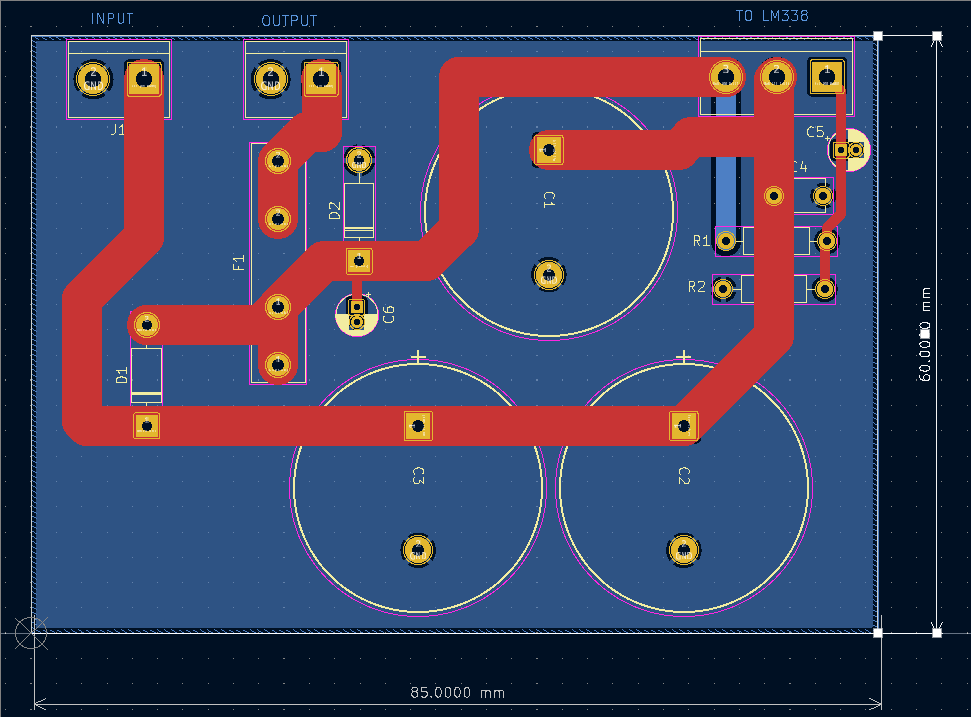
The PCB layout is shown below. Red is front, blue is back side. All external connections are taken out on screw terminals. This will allow me to change out the controller without any trouble if I want to experiments with other control types.
The 3D view of the board is shown below. I will 3D print a plastic bracket to go on the floor of the chassis and hold the PCB vertically with the screw terminals along the top.


No comments:
Post a Comment