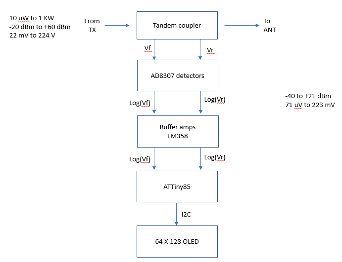
This is a block diagram for a log amp based SWR meter.
- The meter uses a tandem coupler with 20:1 current sampler coils
- AD8307 log amps are used to convert RF signal amplitude from the coupler to log based DC voltage. The log amp outputs are buffered by LM358 op amps to prevent loading the log amps.
- The log amp outputs are fed to an ATTiny85 8 pin Atmel MCU. The ATTiny85 digitizes the log signals and displays output power and SWR.
- The calculated SWR and Output power are displayed on an OLED.
click to enlarge
No comments:
Post a Comment