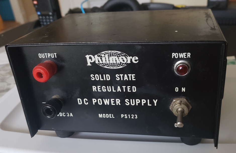
I am working on repairing or restoring a Philmore PS123 DC Power Supply, photo below. The unit nominally outputs 12 volts at up to 3 amps.
I believe this unit is from the mid 1960s and was maybe sold as a way to power 12V automotive CB radios off of 120V AC power. It is a good example of very early linear transistor power supplies. It uses PNP germanium transistors in combination with a 14V zener diode.
I don't have a circuit schematic, but I can mostly get the circuit by tracing out the small circuit board in the unit. The emitter of Q1 is connected to ground. Assuming the base-emitter voltage of the transistors is about 0.2 volts, and tracing from GND thru Vbe of Q1, Vbe of Q2, and then the zener voltage, we get the output voltage of 14V- 0.2V-0.2V or 13.6 volts. At high currents the Vbe voltage drops will increase. Probably at high currents the output voltage will sag down a few hundred millivolts.
I am planning to replace this circuit with a LM338 based regulator board

No comments:
Post a Comment