Showing posts with label AD8307 SWR meter. Show all posts

Tuesday, June 20, 2023

SWR Meter (14) - Box rear panel for SWR coupler

 I am modifying the rear panel of the 3D box to accomodate the shielded SWR directional coupler. The back panel is being modified into a box that holds the two sides of the coupler.

Rear view of modified panel:


Front view of modified panel: 

click to enlarge


Front view with cover removed, showing the two coupler compartments: 

click to enlarge

The lower compartment will have UHF connector inputs and outputs from the rear.  The upper compartment will have forward and reverse outputs, either through twisted pair connections are through SMA connectors. 

Developing....

SWR Meter (13) - 3D printed box parameterization fixed

 I started over with the parameterization of the box.  After watching a Youtube video on parameterizing hole patterns, I was able to figure out how to get the hole patterns to work correctly with the parameters.   3"W by 5"L by 2" H box is shown below.   The hole pattern algorithm needs a starting offset distance from the edge of the panel to the first hole for each direction W, H, and L.  Then an equation determines the number of holes and the interval in between:


The paramters for this box are shown below.   

  • boxH, boxL, boxW:  parameters are the box outer dimensions
  • thick1, thick2:  parameters are panel thickness parameters
  • ??hole: parameters are for the screw holes,  clearance and tap
  • offset?:  parameters are the offset distances to the first hole for H, W, and L
  • nscr?:  parameters are the equations to determine the number of holes and interval between holes.

click to enlarge

Here is the same box with the length set to 3 inches.  Notice the number of holes along the length has been reduce from 5 holes to 3 holes

click to enlarge


Thursday, June 15, 2023

SWR Meter (12) - 3D printed box parameterization problems.

Using Fusion 360, I have attempted to parameterize the design of the RF tight project box that I designed for the SWR meter.  The parameters I've used are: 

  • width, length and height of the box
  • thickness of the panels
  • countersunk clearance hole parameters
  • self tapping screw pilot hole paramters
  • L: length of the box
  • H: height of the box
  • W: width of the box
It takes some experience to find the most efficient way of implementing the paramters.  The challenge right now for me is to get the screw locations to automatically adjust to the changes in the box dimensions and panel thickness. 

The photo below shows the SWR box after changing the box height from 1.5" to 2".  Note the row of screw holes on the side of the box is now in the wrong place.  So the challenge is to set up an equation to parameterize the screw hole locations.   

Developing....


click to enlarge

Wednesday, June 14, 2023

SWR Meter (11): Sheet metal box progress

 Continuing frorm SWR Meter (9)   we have built the first prototype of a sheet metal box for the SWR meter.  The box is made from 22 ga weldable steel for the bottom and 26 ga weldable steel for the top. Note that the holes have been drill for attaching the top to the bottom, The row of holes along the top are for fastening the top to the internal dividers. The inside dimension of the top is about 1 mm too wide.  That's not bad but we still need to work on making predictable bends. 

click to enlarge

The photo below shows the interior of the box, with a 3D printer divider (green plastic) mounted to the botoom.   

click to enlarge


Monday, June 12, 2023

SWR Meter (10) - 3D printed project box design in Fusion 360

 I tried another SWR project box design using 3D printing rather than a sheet metal box.  The design philosophy is as follows: 

  • Use flat panels as the box components, no U shapes or L shapes.
  • Use 0.113" (3mm) panels
  • Use countersunk #2-28 self tapping screws to assemble the panels together.
  • Use enough screws spaced close together to ensure no open cracks along the seams where the panels join.
  • All inside surfaces should be flat to facilitate laying copper or aluminum tape on the inside surfaces. 
  • Copper tape on the inside surfaces should form a continous conductive surface inside the box to be RF tight.

The resulting box is show below, it is 3" wide, 1.5" high, and 5" deep.

click to enlarge
You can see the places where the #2 countersunk screws are used.   there are quite a few of them. 

The drawing below shows the box exploded into two sub assemblies of 3 components each.  

click to enlarge

After 3D printing the resulting box is shown in the photo below. 

click to enlarge

The box has a few problems: 
  • There are a LOT of screws.  I only installed every other screw.
  • The Torx drive on the #2 screws doesn't really drive the screws well. The driver slips out of the screw head often.
  • Driving the self tapping screws into the edges of the 3 mm thick panels tends to cause the panel surface to dimple.
Even with problems above the box will probably be practically useful.   Next I will work to fit the SWR meter parts into the box. See the photo below.  I will need to add a couple of divider shields. From left to right, the SWR coupler will be installed on the back wall of the box. The logarithmic detector PCB will be mounted on the floor of the box, which the OLED display and the ATTiny85 controller will be mounted on the front of the box. 

click to enlarge


Monday, May 22, 2023

SWR Meter (9) - Project box design in Fusion 360

 This is my first cut at the SWR project box design.  I used the sheet metal options in Fusion 360 to design a two piece sheet metal box with dividers. The box is 3" wide by 4.5" deep.

click to enlarge


 The division of the box into shielded compartments can be seen with the top removed.  Four pieces are cut from 0.8 mm aluminum: 1) the base, 2) the top, and 3) the dividers.

click to enlarge


The sheet cutout patter for the base is shown below. Dimensions in mm.

click to enlarge


Cutout pattern for the top are shown below.  Dimensions are in mm. 

click to enlarge


Cutout pattern for the basic divider is given below, later versions may need a separate version for each divider.  Dimensions are in mm. 

click to enlarge


Friday, May 19, 2023

SWR Meter (8) - Project box

 I am going to make the SWR meter enclosure out of sheet metal, and do the drafting in Fusion 360.

The plan for the enclosure is shown below: There needs to be a conducting shield between the tandem coupler and the log amp board.  I'll use bulkhead mounted SMA connectors to feed the RF signals.   I'll also put a shield between the detector board and the MCU/Display section.  A 9V battery will go in the MCU section.  Front panel controls will be a small battery switch, and a cutout for the OLED display.


Saturday, May 6, 2023

SWR Meter (7): Test results of log amp detector

 I ran tests on the response of the SWR detector PCB.  Everything appears to function well. The response graph is shown below

click to enlarge

It looks like I've got the noise problems worked out.  The response is very close to what is given in the data sheet.  There is a jog in the response at about -50 dBm.  This jog is there because I had to switch to an attenuator to get signals down below -50 dBm.  The attenuator changes the load on the signal generator slightly, resulting in the slight offset in response below -50 dBm.

click to enlarge

I am designing the circuit to measure power up to 300W.  The amplitude of the Vr port on the coupler is: 

$V_R=\frac{\sqrt{PR}}{N}$

where: 
  • P is the power on the load
  • R is the load resistance (50 ohm)
  • N is the number of turns on the current transformer of the coupler. (20)
This gives an RMS voltage of 6.1 volts for VR for 300W on the load. 

The AD8307 datasheet define dBm as:

$dBm =10\log_{10}\left( \frac{V_{RMS}^2}{R}\cdot 1000 \right)  $

Using this formula,  6.1 volts is 28.7 dBm.   In order to keep the dBm input to the AD8307 to under 10 dBm,  I will add a 20 dB attenuator between the coupler and the AD8307.


Friday, April 28, 2023

SWR Meter (6): PCB populated, ready for testing.

 I have populated the SWR detector  PCB. The 0603 capacitors and resistors are about the size of sesame seeds and require a lot of care to install.  With a little practice it seemed I was able to solder them to the board fairly well. 

I set out a white paper napkin to hold the parts before soldering.  The white napkin has good contrast with the tiny parts so they are easier to see and handle. I used a small Ungar Princess soldering iron with a very sharp point.  I pair of tweezer is necessary to pickup and position the parts. I used ultrafine 0.3 mm diameter solder. To solder a 0603 part on the board, first solder a small dab of solder on one of the pads. Pick up the part with the tweezers and place it in position, one end on top of pad with the small dab of solder, the other end of the parts goes on the other unsoldered pad.  Heat the soldered pad until the solder melts, then continue until the part itself heats up and wets with solder. The part will self-center on the soldered pad. After letting the pad cool. Solder the other pad to the part. 

click photo to enlarge

I tested the voltage regulator on the board. It produced 5V whenever the input voltage exceeded 6.5 volts. 


Tomorrow I'll start testing the rest of the board.

Thursday, April 27, 2023

SWR Meter (5): PCB arrives from PCBWAY!

 The circuit boards for the SWR project came in. Click to enlarge. 


I will start work populating the board tonight. 

Monday, April 24, 2023

SWR Meter (4): PCB layout done, PCB ordered

I have finished the PCB layout for the SWR meter.  The SWR meter circuit is given again below for reference Click for full sized image. The circuit consists of two identical channels. The forward voltage channel is J1 to log amp U3 to voltage follower U1A.  The corresponding reverse voltage channel is J2 to U2 to U1B.  A regulated 5V supply is provided by U4.  

The diagram below shows the KiCad circuit board layout for the circuit, looking from the top of the board.  Red traces are top copper, and blue traces are bottom, which is mostly the ground plane. 
The Vf and Vr signals come in on SMA connectors at the left edge of the board. The log amps U2 and U3 are SOIC surface mount devices.  The buffer amps are in the dual DIP package U1.  The output signals for Vf and Vr go out J5 and J6 respectively.    I used through hole inductors L1 and L2 for isolating the DC supply from the log amps.  DC signals are sent off board using 0.1" headers J3, J4, and J5.  All the capacitors and resistors are 0603 SMD parts.  These 0603 parts may turn out to be too small to handle.  I still have not tried practice soldering of these parts.  

The figure below shows the KiCad generated 3D image of the board.   I really love the 3D image feature of KiCad, it's very helpful for sizing board size before ordering.   You can plainly see the rf coax inputs on the left, the going right the log amps U2 and U3, the dual buffer amp U1, and finally the measured forward and reverse signals coming out the headers on the right edge of the board.  

The board was ordered from PCBWAY on April 14.  After clearing up a question about solder mask on one part (my mistake),  the sent me a note that the board had been completed and shipped.  For low cost I elected for USPS shipping.  I believe the board should arrive sometime the first week of May.  I have two more PCBs to order: 1) the control board for the Philmore 12V supply, and the NE602 direct conversion receiver.  

SWR meter (3): Forward and reverse voltage detector designed.

 I have put together a circuit for the SWR meter, shown below.  Click for full size. Two power measurement channels are shown.  Top channel is for forward power and below that is the circuit for the reverse power.  A small 78L05 linear regulator is also included.   Each channel has an AD8307 logarithmic amplifier followed by an LM386 op amp unity gain follower.  I plan to put the circuit in a well shielded enclosure.  I have included surface mount bypass capacitors on the board, but I've also ordered some cabinet mount bypass capacitors from AliExpress.  


Wednesday, March 29, 2023

SWR meter (2): Coupler built and tested

 Here is a photo of the coupler as built. I 3D printed the box, which is 50mmW X 50mm L X 28mmH. About 2in by 2in by 1 inch.   I box is designed with removable dividers that can be lined with aluminum foil.   This didn't work out too well because the aluminum foil tears while tightening the nuts on the BNC connectors.


I did some testing to measure the accuracy of the coupler.  It was a little bit disappointing at the high frequencies, however further checking shows that the test setup isn't really good.  I'm going to wait until I have some decent interface electronics to measure Vf and Vr, rather than trying to use my scope. 


Tuesday, March 28, 2023

SWR meter (1)

 I'm in the process of building an SWR meter.  The directional coupler is the "tandem type as shown below. 

This is a very simple circuit that is fairly easy to build.  It consists of two current transformers TR1 and TR2.   Each transformer has a 1 turn "current" side and  N turn "voltage" side.  In my case I chose  to use FT50-61 cores with 20 turns on the voltage side.   These cores have an AL of 69 uH per N^2/1000, where N is the number of turns.  This turns out to be 27.6 uH on the voltage side and 0.069 uH on the current side. 

I simulated the the coupler using LTSPICE as shown below, click to enlarge: 
Note that I've used parameter Lx to be able to change the inductance of the voltage side of the transformers. I did this in order to determine minimum inductance needed for the coupler to work at a given low frequency.  For the current side of the transformers, the inductance is Lx/400, since the turns ratio is 20:1.  I measured the self resonant frequency of the transformer and added 10 pF of stray capacitance across the windings (C1 and  C2)

Upon simulation this circuit, using 22 uH on the transformers:
The excitation voltage V1 is 1 volt. 
As shown, the load is perfectly matched and Vr should be zero.
Upon simulation: 
The voltage Vf = 49.875 mV.  It should be Vin /20 = 50 mV
The voltage Vout 997.5 mV

The response is flat from 1 MHz to 100 MHz for a matched load.  
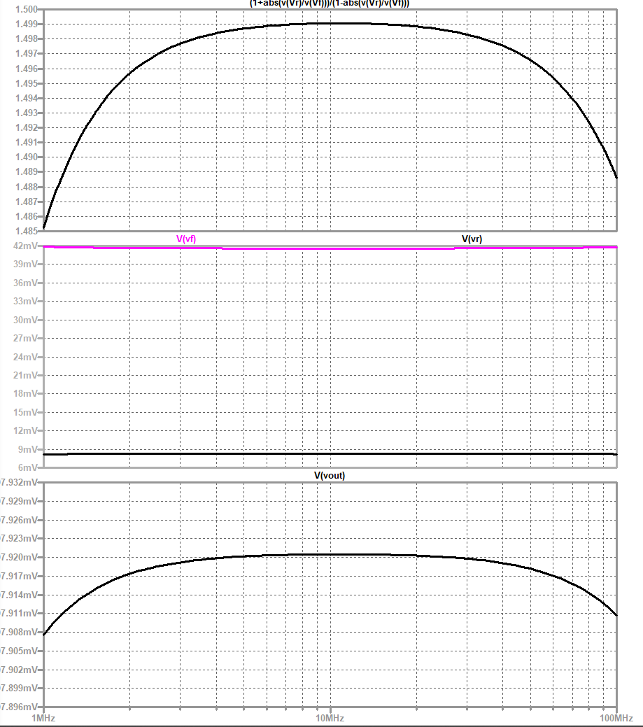
If I change to a mismatched load of 75 ohms,  the frequency response is affected.  In the plot below (click to enlarge), the load voltage is plotted at bottom, measured forward and reflected voltages in the center plot, and measured VSWR in the top plot.  The nominal sensed forward voltage should be 50 mV, but is measured as ~42 mV, Vr should be 10 mV but is measured at 9 mV
VSWR should be 1.5, and at 10 MHz is measured at 1.499.  Additionally the accuracy of the VWSR measurement falls off at low and high frequencies. 


Changing the load to 150 ohms, the simulated response is shown below.  
Nominal load voltage 1V, simulated 0.998V
Nominal Vf:  50 mV, simulated 32.5 mV
Nominal Vr: 25 mV, simulated 17 mV
Nominal VSWR: 3.0, simulated 2.99


Monday, February 27, 2023

SWR Meter (0): Plan for SWR meter

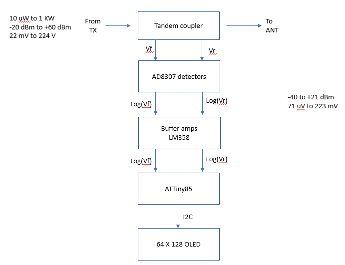
 This is a block diagram for a log amp based SWR meter.
  1. The meter uses a tandem coupler with 20:1 current sampler coils
  2. AD8307 log amps are used to convert RF signal amplitude from the coupler to log based DC voltage.  The log amp outputs are buffered by LM358 op amps to prevent loading the log amps.
  3. The log amp outputs are fed to an ATTiny85 8 pin Atmel MCU.  The ATTiny85 digitizes the log signals and displays  output power and SWR.  
  4. The calculated SWR and Output power are displayed on an OLED. 

click to enlarge