Showing posts with label Tuna Tin S. Show all posts

Wednesday, December 21, 2022

Tuna Tin S (9) Installing screw inserts in cabinet

 Still learning Fusion 360, a rocky experience, I designed a simple test block to practice putting M3 inserts in 3D printed cabinets for the Tuna Tin S. 

The inserts were ordered off Amazon  Here's a link. 

The test block is PLA material and consists of an array of 4 mm diameter holes in a 10 mm thick block. The infill is set to 20%, and the wall thickness set to 0.8 mm. 

I used a 10 Watt Ungar Princess model soldering iron.  According to Ungar's 1967 catalog it was newly introduced for microelectronic soldering at the time.  The heating element has, according to the catalog, has a tip temperature from 550F to 650F.  The soldering iron belonged to our grandmother, Ruth Chandler, who was an assembly worker at Dorsett Electronics in Tulsa in the 1970s.  So the iron is around 50 years old  ;-)  . 


I placed the insert tapered end outward on the tip of the soldering iron. 


I let the insert heat up for awhile, then inserted it into the hole of the test piece.  It sinks into the test piece gradually,  and I stopped when the top of the insert was even with the surface of the test piece.  Alignment doesn't seem to be much of a problem.  A recommendation from a YouTube video, linked here, is to stop inserting the insert when the top is just above the surface of the plastic, and then do final placement pushing the insert flush with a flat tool like a hammer's striking surface.   I tried that way and it worked well.  I also tried just doing the whole thing freehand and didn't see much difference in alignment.  The screws I used were 8 mm long M3 screws. 

The screw is driven by an Allen wrench.   I can exert quite a bit of torque, as shown in the photo below, and the insert holds without breaking the plastic.

I'm planning to use these M3 inserts, along with M2 inserts to design all 3D printed cabinets for projects going forward. 


Friday, December 16, 2022

Fixing KY-040 rotary encoder problems interfacing to Wemos D1 Mini

 I am in the process of building  a version of AK3Y's Tuna Tin S, which is presented in December 2020's QST.  The attractiveness of the project is to replace old style VFO circuits with a low-cost digital synthesizer. I decided to use a Wemos D1 Mini clone for the synthesizer control, rather than the Arduino Nano shown in the QST article. I was able to get the D1 Mini, Si5351 synthesizer breakout, and the KY-040 rotary encoder going pretty quickly on a bread board.  

After building a second version wired on a PCB, I noticed that when rotating the encoder knob that the unit was counting frequency up and down erratically.   Upon investigation, I found that the encoder had a great deal of switch bounce that was causing misclocking of the counting algorithm in the controller.  The photo below shows the signal from the encoder CLK line transitioning from low to high with about 15 usec of switch bouncing. The switch bounce can cause havoc with the rotary encoder counting routine in the controller.  Misclocking caused by switch bounce tends to cause the counter to count erratically. 

I downloaded AK3Y's Nano program which is written in Arduino IDE, and ported this code over to the D1 Mini.  In the article and program,  the encoder CLK and DT lines are tied to digital input of the Nano.  The CLK falling edge  generates an interrupt.  The interrupt routine is shown below:  

There is some debounce code added to ignore interrupts that occur within 5 ms after a previous interrupt.  The frequency gets changed in the interrupt routine.  In the main loop if the frequency  changes (caused behind the scene during interrupt), then the synthesizer and display are updated with the new frequency.
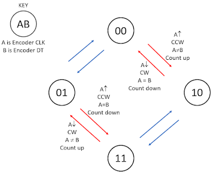
The principle of operation can be understood by examining the encoder state transition diagram. In the diagram below, the encoder CLK and DT are denoted A and B respectively in the state transition diagram. The encoder signals transition 00 to 10 to 11 to 01 to 00 when rotating clockwise and rotate 00 to 01 to 11 to 10 to 00 rotating counterclockwise.  When encoder CLK,  which is A, falls it corresponds to the transitions colored red in the diagram.  In the lower left, A (CLK) falls, and B (DT) is HIGH when the transition is finished.  This transition indicates a clockwise rotation and should generate a count upward. In the upper right transition, A (CLK) falls, and at the end of the transition B (DT) is LOW.  This transition is counterclockwise and should generate a count downward.  Looking at the interrupt code, which is entered immediately after the fall of encoder CLK, the routine checks DT.  If DT is LOW the frequency is decremented, otherwise the frequency is incremented. 


I ported this algorithm to the D1 Mini, but upon testing, the frequency counted erratically when the encoder was rotated.  I put the encoder up on the scope for diagnosis.  For trouble shooting purposes I added a test output of the D1 Mini.  This signal falls immediately after the DT is read in the interrupt routine and rises again immediately after the display and the Si5351 synthesizer are updated. I also added the 0.68 uF capacitor on the encoder CLK line. This capacitor is recommended in the AK3Y QST article.

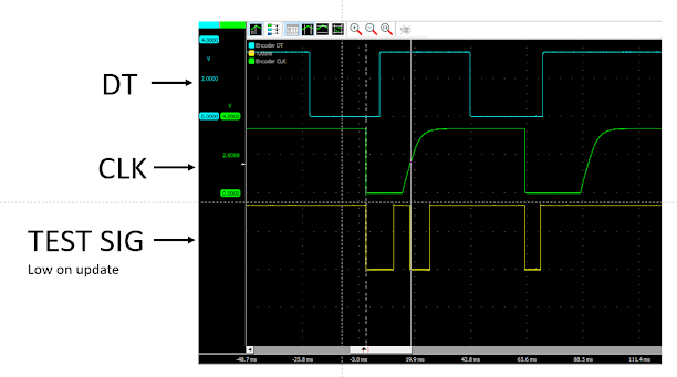
The resulting test signals are shown in the diagram below.  The encoder knob was turned two detents counterclockwise over a time interval of about 75 ms.  Note that when CLK (green curve) falls, the TEST SIG (yellow curve) goes low, indicating that the interrupt was triggered and the display and Si5351 were updated.   However the problem is that the rising edge of CLK also triggered an interrupt, as indicted by the fall of TEST SIG.  This is shown at the vertical white line in the diagram.  The interrupt pin is specifically setup to trigger on the falling edge of CLK, but often triggers on the rising edge as well. This causes erratic counting in response to turning the encoder knob.  
The false triggerings are probably a result of the slow rise of the CLK signal.  It is not good practice to drive digital inputs with slow moving signals.  The problem was repeatable and occurred using two different D1 Minis.  I did not try switching out to a different encoder.  It is possible that the Arduino Nano used by AK3Y didn't experience this false interrupt triggering. 

I did some more research and found some inspiration on the Components101.com site.  Follow the link and you'll find a KY-040 encoder datasheet and a good discussion of its construction and operation.  The test program included with the datasheet used a different algorithm for converting the encoder signals to counts. 

Observe the annotated encoder state diagram below.  Anytime CLK changes, whether rising edge or falling edge, we can determine the direction of rotation by observing whether the DT signals is the same as CLK, or whether DT is opposite of CLK.  In the first case the movement is counterclockwise and the count should be decremented, in the second case the movement is clockwise and the count should be incremented.  


I decided to abandon the use of interrupts and determine CLK transitions by polling. I also removed the capacitor off the CLK line. The loop section of the D1 Mini program is shown below.  After a check of the encoder push switch, the encoder service section begins at line 73.   If a check of the CLK signal shows a transition has occurred, then the encoder service routine is executed, otherwise the loop is begun again.  The encoder service is simple.  The DT signal is compared to CLK to determine the direction of rotation and the count (in this case a frequency variable) is incremented or decremented accordingly. After that, the display and the Si5351 are updated.  A diagnostic test output is toggled to indicate on the oscilloscope that the encoder service routine is active. 


The scope traces are shown below. In this case the encoder is rotating counterclockwise. As shown by the test signal, the encoder service routine is entered at every transition, up or down, of the CLK signal. After each transition CLK is always the same state of DT, so the count is decreasing as the knob rotates counterclockwise.  

Other tests at very fast time scale show that the latency for detecting a CLK transition by polling is less than 10 us.  This is sufficiently fast to avoid misreading the DT signal.  

Further the encoder service routine last about 6 ms before the routine returns to polling for a CLK transition again.  This is a sufficient delay to provide debounce of the encoder CLK signal.  The routine responds to the first valid transition in a bouncy transition and ignores other bounce transitions since it is away on the encoder service routine. 


Monday, December 12, 2022

Tuna Tin S (8). Cabinet Version 2

Son Sam sent a corrected stl file and I printed it out and mounted the board to it.  See photo below.
Everything lines up well now. Just a couple of adjustments needed. 
Below shows the alignment of the front panel parts.  Pretty good. 

Below shows view from the rear.  Mount screws go in well.


Sunday, December 11, 2022

Tuna Tin S (7), 1st try cabinet

Here's the first try on the cabinet. My son Sam and I designed it on Fusion 360, and I printed it out on my 3D printer.  See the photo below. The hole for the encoder was located in the wrong place. As can be seen,  I opened the encoder opening up with a nibbling tool.  The back view is below

The PCB is pushed forward to lock into slots behind the front panel, and two mounting screws at the back corners hold the PCB down. I didn't leave enough room under the PCB for the wiring, so we'll have to increase the dimension.  I used M4 machine screws as self tapping screws and they seem to do the job.  We'll try the corrected version tomorrow. 


Tuna Tin S (6), Wired up, ready to test.

 Finally got the synthesizer board wired up and checked.  The 1st photo show the board top side. 

The second photo shows the board underside.  The wiring was done with 28 AWG wirewrap wire, soldered pin to pin. 

The next task will be to design a box for it and get it mounted.  I need to check the power supply draw and maybe add some power supply filtering.   Presently, everything is powered through the D1 Mini USB connection.  The USB supplies 5V and the D1 Mini had a 3.3V regulator that supplies the ESP8266 controller and the other components in the unit: 1) OLED display, 2) Si5351 synthesizer, 3) rotary encoder.

I have a 10W linear amplifier on order from QRP Labs.  It's on it way from Turkey.  When it comes in we'll put it together and then drive it with this synthesizer and try some 40meter QRP activity.


Saturday, December 10, 2022

Tuna Tin S (5), Component placement & schematic

 I have populated the PCB for the Tuna Tin synthesizer, see the photo below.  I considered crowding the components more and cutting off the excess PCB area, but will just use this roomy component layout for adaptability.  Also I'm using this board for learning and practice.   See the photo below. 


I constructed the schematic to use when I wire the board.  See the diagram below. The schematic was entered using KiCad.  I had to construct symbols for the graphic dispay, the encoder, and the Si5351 breakout module. I'll need to add a 5V to 3.3 supply at some point, but for now it's being powered through the D1 Mini's USB port. 


Thursday, December 8, 2022

Tuna Tin "S" (4), RF synthesizer, move to PCB

I've come to the point where I need to move the RF synthesizer to a PCB.  I am going to mount the encoder, D1 Mini, OLED, and Si5351 board all on a 60mm by 80 mm board.  I'll put the display and encoder on one edge to interface with the operator through a box wall.  I'm going to 3d print the box later,  but I'm considering a shielded metal box, or something made out of clad PCB panels. 

The photo below shows the candidate PCB.  I got the PCB from an assortment sold on Amazon.com Link  I still have to add a 3.3 volt power supply to the circuit.  For this I'll need to measure the total current draw of all the components. 


Tuesday, December 6, 2022

Tuna Tin "S" (3), RF synthesizer (Updated)

 With a little work, I've now added the Si5351 synthesizer to the project. The photo below shows the  breadboard.  The frequency is set to 7006.00 kHz 

The output, shown below,  is 7005.98 kHz.  So its off by 20 Hz. 


Update: I was able to add a wire from the encoder switch to the D1 Mini to implement the coarse/fine control on the encoder.  Now the coarse setting is 1 kHz steps, and the fine setting is 100 Hz steps, and pressing the encoder knob to activate the encoder switch toggles the steps between coarse and fine.

Monday, December 5, 2022

Tuna Tin "S" (2) Encoder & display

As shown below I got the encoder and the display working together.  


Sunday, December 4, 2022

Tuna Tin "S" (1) (Updated)

 After spending a lot of time going over my old projects from the 80s I realized that they projects were way out of date...   Making HF receivers and transmitters,  the variable capacitors and turns reducing dials proved to be so expensive.  The variable cap is maybe \$25 if one can even be found, and vernier dials are selling for something like $45 each.  The question is: What is the modern way to build HF projects?

I came across an article in this month's (Dec 2022) QST titled "A Simple CW QRP Transceiver for 40 Meters" by James Forkin.  In my opinion,  the "simple" transceiver isn't all that simple,  but the article did point to an earlier article that provided a string of references to some simple projects that capture the essence of modern HF receiver and transmitter design.  In the end I zeroed in on a December 2020 QST article by Bob Fontana, AK3Y, "The Tuna Tin "S" - A Bare-Bones Synthesized QRPp Transmitter."  The transmitter basically is a  synthesized RF source driving a simple IRF512 MOSFET power stage.  

This simple project can easily been divided into to tasks: 1) Build the synthesized RF source and 2) build the power stage to drive the antenna.  The latter task has some challenges, in particular finding modern power devices for the design.  Otherwise the power stage design is a fairly straightforward task with many examples in the literature and on the web.

But at this point I want to focus on building the synthesized RF source.  This is a new technique for me, so it should be a learning experience.  The technique is very cheap,  I believe it can be built for less than $10 with a little effort.  

The basic block diagram of the RF synthesizer is shown in the figure above, which is Figure 1 from the article. In the upper right is an Si5351 synthesizer module, which produces the RF signals in response to commands from the Arduino Nano controller on the left.  A KY-040 rotary encoder is used by the operator to select the desired RF frequency by rotating the encoder knob up or down. The Nano responds to the encoder by changing the RF frequency of the Si5351 and displaying the frequency on the OLED display module.  

For my version of this RF synthesizer, I plan to use a Wemos D1 Mini clone instead of the Arduino Nano.  The D1 Mini is a very small ESP8266 based development board.  Those familiar with the 8266 know it has its own WIFI transceiver and antenna. I bought 5 of these for $16 off of Amazon and used them to build WIFI based temperature sensors to use around the house.   For this project I won't use the WIFI unit on the D1 Mini.

I ordered the other parts of the RF synthesizer from Amazon:  1) 0.96" OLED 128x64  (5 for $15),  2) Si5351 RF synthesizer module (2 for $8), and 3) KY-040 rotary encoders (5 for $9).  All told the total cost for the parts for 1 unit is about 3+3+4+2 dollars.  That's $12 per unit.  That's not bad for a wideband, rock stable RF source for transmitter and receiver projects. Beats the cost of a variable capacitor and vernier dial for sure. 

I tested the encoder last night by powering it up and observing the signals on my o-scope.  I put the parts on a protoboard and started testing the OLED.  Unfortunatly,  I'm having some problems getting the software library loaded,  so that's where I left it. 


 Update 4Dec22 13:55
Finally got the display going.  Note the "Hello world" on the display below....