Friday, April 28, 2023

SWR Meter (6): PCB populated, ready for testing.

 I have populated the SWR detector  PCB. The 0603 capacitors and resistors are about the size of sesame seeds and require a lot of care to install.  With a little practice it seemed I was able to solder them to the board fairly well. 

I set out a white paper napkin to hold the parts before soldering.  The white napkin has good contrast with the tiny parts so they are easier to see and handle. I used a small Ungar Princess soldering iron with a very sharp point.  I pair of tweezer is necessary to pickup and position the parts. I used ultrafine 0.3 mm diameter solder. To solder a 0603 part on the board, first solder a small dab of solder on one of the pads. Pick up the part with the tweezers and place it in position, one end on top of pad with the small dab of solder, the other end of the parts goes on the other unsoldered pad.  Heat the soldered pad until the solder melts, then continue until the part itself heats up and wets with solder. The part will self-center on the soldered pad. After letting the pad cool. Solder the other pad to the part. 

click photo to enlarge

I tested the voltage regulator on the board. It produced 5V whenever the input voltage exceeded 6.5 volts. 


Tomorrow I'll start testing the rest of the board.

Philmore PS123 Power Supply (3): LM338 controller circuit and PCB

 Until I get some more information to restore the Philmore PS123 power supply, I'm going to install a modern controller circuit in it and use it on my bench. The circuit is shown below.  


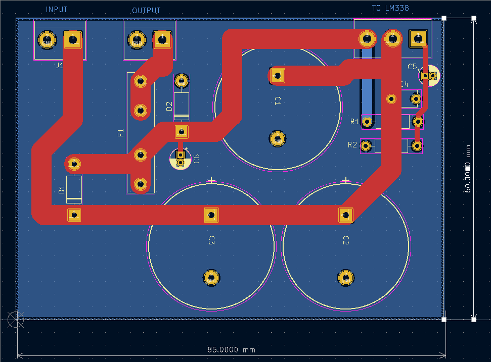
I got the input filter capacitors at Affiliated Electronics in Tulsa.  The combined capacitance is 9900 uF, which might cause some current inrush problems.  My measurements on the winding resistance of the transformer indicates the inrush currents will be about 30 amps on the secondary, and 5 amps on the primary mains circuit. D1 and D2 are transient protection for the LM338. The LM338 controls for a 1.25 volt reference voltage from Vo to the ADJ terminal.   The R1-R2 voltage divider is designed so that when the 1.25 volts appears (across R1)  the voltage across R1-R2 in series (the output voltage) will be 12 volts.  This is a straightforward circuit and is close to what is recommended in the LM338 datasheet. 

I moved the fuse from the cabinet mounted holder onto the PC board.  This will be me more room in the cabinet.  I plan to also add an 3 conductor AC cord to ground the chassis, and also add an inline mains fuse. 

The PCB layout is shown below.  Red is front, blue is back side. All external connections are taken out on screw terminals.  This will allow me to change out the controller without any trouble if I want to experiments with other control types. 


The 3D view of the board is shown below. I will 3D print a plastic bracket to go on the floor of the chassis and hold the PCB vertically with the screw terminals along the top.


Thursday, April 27, 2023

Philmore PS123 Power Supply (2): description of unit as found

 I continue to work on the Philmore 12V Power Supply.  Below is a photo of the inside of the unit.  I've indicated where the diode bridge is connected directly to the output positive binding post of the unit. You can see the mounting location of the TO-3 pass transistor on the back of the chassis behind the transformer. A small circuit board, not shown, mounts on the floor of the chassis to the left of the transformer. 


The top and bottom view of the control PCB are shown below. 

There appear to be several uninstalled components on the board, these were probably components for some sort of short circuit protection.

I found a YouTube video of a bench repair of a PS123, replacing the pass transistor. 
https://youtu.be/5IpG66imsn8

SWR Meter (5): PCB arrives from PCBWAY!

 The circuit boards for the SWR project came in. Click to enlarge. 


I will start work populating the board tonight. 

Wednesday, April 26, 2023

Philmore PS123 Power Supply (1): Control circuit traced out and circuit description

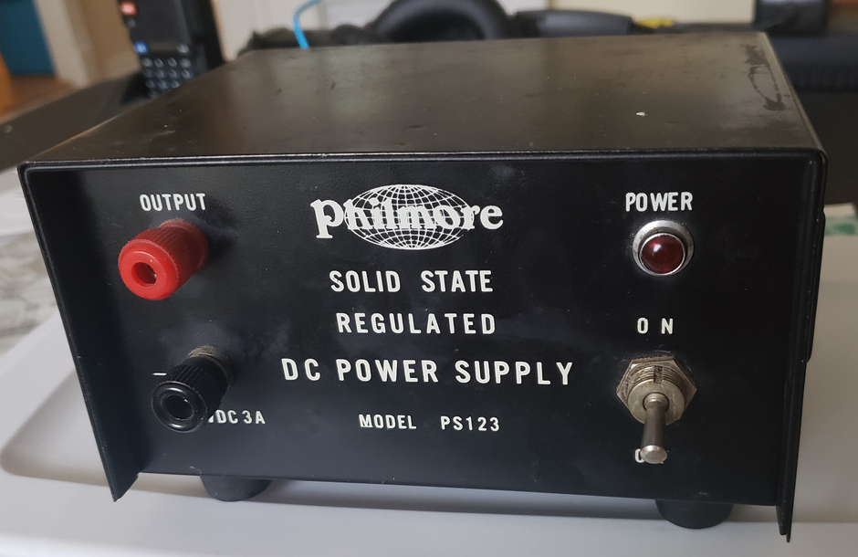
 I am working on repairing or restoring a Philmore PS123 DC Power Supply, photo below.  The unit nominally outputs 12 volts at up to 3 amps.  


I believe this unit is from the mid 1960s and was maybe sold as a way to power 12V automotive CB radios off of 120V AC power.  It is a good example of very early linear transistor power supplies.  It uses PNP germanium transistors in combination with a 14V zener diode.  

I don't have a circuit schematic, but I can mostly get the circuit by tracing out the small circuit board in the unit. The emitter of Q1 is connected to ground.  Assuming the base-emitter voltage of the transistors is about 0.2 volts, and tracing from GND thru Vbe of Q1, Vbe of Q2, and then the zener voltage, we get the output voltage of 14V- 0.2V-0.2V  or 13.6 volts.  At high currents the Vbe voltage drops will increase.  Probably at high currents the output voltage will sag down a few hundred millivolts. 

I am planning to replace this circuit with a LM338 based regulator board


Monday, April 24, 2023

SWR Meter (4): PCB layout done, PCB ordered

I have finished the PCB layout for the SWR meter.  The SWR meter circuit is given again below for reference Click for full sized image. The circuit consists of two identical channels. The forward voltage channel is J1 to log amp U3 to voltage follower U1A.  The corresponding reverse voltage channel is J2 to U2 to U1B.  A regulated 5V supply is provided by U4.  

The diagram below shows the KiCad circuit board layout for the circuit, looking from the top of the board.  Red traces are top copper, and blue traces are bottom, which is mostly the ground plane. 
The Vf and Vr signals come in on SMA connectors at the left edge of the board. The log amps U2 and U3 are SOIC surface mount devices.  The buffer amps are in the dual DIP package U1.  The output signals for Vf and Vr go out J5 and J6 respectively.    I used through hole inductors L1 and L2 for isolating the DC supply from the log amps.  DC signals are sent off board using 0.1" headers J3, J4, and J5.  All the capacitors and resistors are 0603 SMD parts.  These 0603 parts may turn out to be too small to handle.  I still have not tried practice soldering of these parts.  

The figure below shows the KiCad generated 3D image of the board.   I really love the 3D image feature of KiCad, it's very helpful for sizing board size before ordering.   You can plainly see the rf coax inputs on the left, the going right the log amps U2 and U3, the dual buffer amp U1, and finally the measured forward and reverse signals coming out the headers on the right edge of the board.  

The board was ordered from PCBWAY on April 14.  After clearing up a question about solder mask on one part (my mistake),  the sent me a note that the board had been completed and shipped.  For low cost I elected for USPS shipping.  I believe the board should arrive sometime the first week of May.  I have two more PCBs to order: 1) the control board for the Philmore 12V supply, and the NE602 direct conversion receiver.  

SWR meter (3): Forward and reverse voltage detector designed.

 I have put together a circuit for the SWR meter, shown below.  Click for full size. Two power measurement channels are shown.  Top channel is for forward power and below that is the circuit for the reverse power.  A small 78L05 linear regulator is also included.   Each channel has an AD8307 logarithmic amplifier followed by an LM386 op amp unity gain follower.  I plan to put the circuit in a well shielded enclosure.  I have included surface mount bypass capacitors on the board, but I've also ordered some cabinet mount bypass capacitors from AliExpress.