Monday, February 27, 2023

SWR Meter (0): Plan for SWR meter

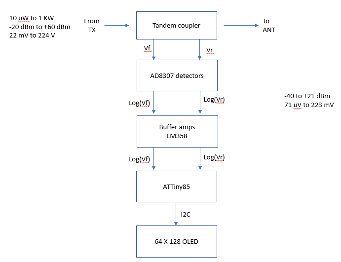
 This is a block diagram for a log amp based SWR meter.
  1. The meter uses a tandem coupler with 20:1 current sampler coils
  2. AD8307 log amps are used to convert RF signal amplitude from the coupler to log based DC voltage.  The log amp outputs are buffered by LM358 op amps to prevent loading the log amps.
  3. The log amp outputs are fed to an ATTiny85 8 pin Atmel MCU.  The ATTiny85 digitizes the log signals and displays  output power and SWR.  
  4. The calculated SWR and Output power are displayed on an OLED. 

click to enlarge

Saturday, February 18, 2023

Adding the transmitter switch and LP filter carrier

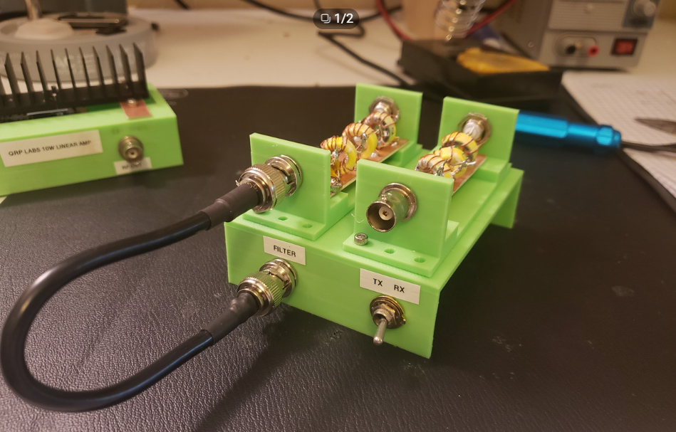
 The radio is growing.  At this point I've got the Si5153 synthesizer built, 10W amplifier, the 20m and 40m LP filters, and now I've added the TX/RX switch combined with a carrier for the LP filters. 

Next up is the SWR meter. Front view of TX/RX/LPF Carrier is below.  Click to enlarge


Rear view of the unit is below


Sunday, February 12, 2023

Integrating signal source, 10W amp and filters.

 I am in the process of integrating the components of a homebrew radio station from stuff I've built in the last few weeks.  See the photo below.  Click to enlarge.


  1. On the left is the synthesized Si5153 signal source.  It is presently programmed for 40 meters.  I'm going to operate the system as a transmitter for awhile then add a receiver.  For transmit, I'll add 20 meters to the Si5153 source.  When I add a receiver, I'll either give it a separate Si5153 source, or reprogram the existing Si5153 to generate a separate RX source, which can be used for a direct conversion RX or a superhet. 
  2. In the center of the photo is the 10W amp, I put SMA connectors on the input and BNC connectors on the output. Making the SMA jumpers was a big pain in the butt. So was the BNC cable.  Once I build up a supply of SMA and BNC jumpers I guess things will get easier.
  3. The lowpass LC filters on the right.  I set them in 3D printed carriers that can be dropped into a larger chassis, which I haven't built yet. 
  4. The remaining components for this project are: 1) TX-RX switch, 2) SWR meter, 3) antenna tuner, and finally, a receiver.
Next I'll be working on the TX-RX switch, then the SWR meter. 

Wednesday, February 8, 2023

Ramsey Q Amplifier salvage

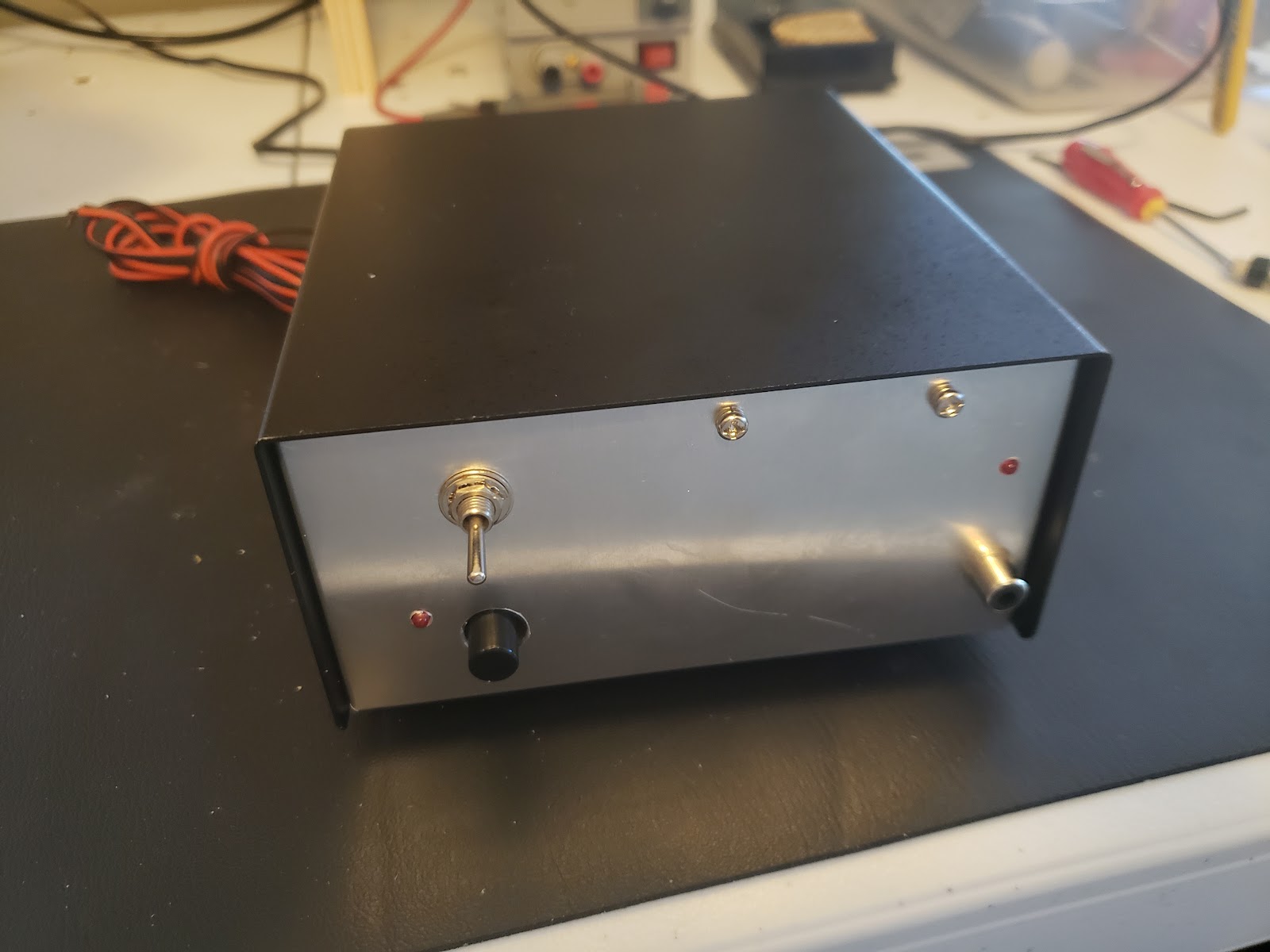
 Yesterday I went to a local electronics store here in Tulsa.  The store has quite a bit of salvage electronics including old tubes and other stuff.  I was looking electronic benchtop components that I could salvage for project boxes. I found three boxes with UHF connectors in the back, which I bought at salvage price.  Opening them up I found a couple of amplifiers that may be useful.  The first is a Ramsey Q Amplifier in what looks like a Radio Shack project box.  The front view is below.  Click to enlarge. 


The RCA connector on the lower right is probably the enable line or for keying.  The switch to upper left is the power switch,  I believe the black push button switch in the lower left is for bypassing the amplifier.   The back view is is shown below and is simply the RF in, RF out, and a post for attaching chassis to ground.


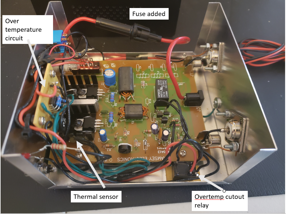
The internal view showing the Q Amp PCB is shown below.  Click to enlarge. 


The amp has some modifications that have been added.  The power connector is wired to a fused pigtail that goes to an external power source.  A temperature sensor is attached to the final transistor heat sink and apparently an overtemperature cutoff circuit has been added, mounted to the bulkhead on the left.  This drives a cutoff relay that's taped to the chassis bottom on the lower right of the photo.  In the upper right of the circuit you can see there's spaces for 3 inductors and 4 capacitors for a 7 pole low pass filter on the RF output before it goes out the antenna connector. 

In the reviews of Ramsey Q Amp in eHam.net, there is quite a bit of criticism of the product and a list of fixes to make it more reliable.  The circuit uses power MOSFETs  as the finals, probable IRF512s, and this appears to be where most of the problems come from. Power MOSFETs are notoriously unreliable when used in linear applications.  The negative threshold voltage coefficient causes thermal runaway and hot spotspots on the die. They also have VHF oscillations if the gates are high impedance. 

I cannot find a schematic online for the Ramsey Q Amp so I may have to reverse engineer a schematic for it.    I suspect the unit works so I look forware to testing it.


Tuesday, January 31, 2023

QRP 10W PA (5): interface to Tuna Tin S (updated with output spectrum)

 The photo below shows the setup to test using the Tuna Tin S with the 10W linear amp. Click to enlarge.


  • The Tuna Tin S is on the left in its green case. It is supplied from a 5V wall wart via a USB micro connector to the Wemos D1 Mini, which supplies regulated 3.3V to the other components in the unit: 1) encoder, 2) display and 3) Si5153 breakout board.  Channel 1 of the oscope is connected to the RF output of the unit. 
  • The RF output of Tuna Tin S is wired to a DC blocking capacitor over to the input of the 10W amp. The amp is supplied with 12VDC from a lab power supply.  A test lead is used to ground the enable control line of the amp to turn it on for testing. 
  • The output of the RF amp is routed to the 40m low pass filter, seen built on the end of a copper clad PCB.  The output of the 40m low pass filter is routed to a dummy load seen on the extreme right of the photo.  Channel 2 of the oscope is connected across the dummy load. 
The test results are shown below, click to enlarge

The input is about 3 Vpp, and is a square wave. There is excessive ringing.   The ringing may be coming from the scope probe, but could also be due to the lack of a resistive termination at the input of the amp. 

The output is 80.8 Vpp,  across a 50 ohm load, which works out to 16.7W  (42.2 dBm) of power.  Previously I tested the amp with a sine input and found I needed a 5Vpp input to drive the amp to 10W output.  I'm assuming for now that the square wave input is driving the amplifier harder, generating an unexpected high amount of power. 

I plan to refine the system by adding an attenuator at the input of the amp to suppress the ringing and lower the input to drive the amp output to 10W.  The RF appears to be getting into my power supply;  the current and voltage meters get erratic when the amp is enabled.  This needs to be fixed.  I'll need to order some chokes and a common mode a filter on the power leads.   I also plan to do an FFT on the output waveform to assess the suppression of harmonics. 

Monday, January 16, 2023

QRP Labs 10W PA (4) -- Designing 20m LC Low Pass Filter

 The circuit for the 20 meter filter for the QRP Labs 10W PA is a scaled version of the 7th order Chebyshev filter for 40 meters, using the same filter table. The component values are given in the schematic.


I do not have 150p NPO capacitors in my stock, So I used 100 pF in parallel with 47 pF.  I used T50-6 cores for the inductors, again with total 300 mW predicted wire and core losses. The LTSPICE predicted filter response is below.

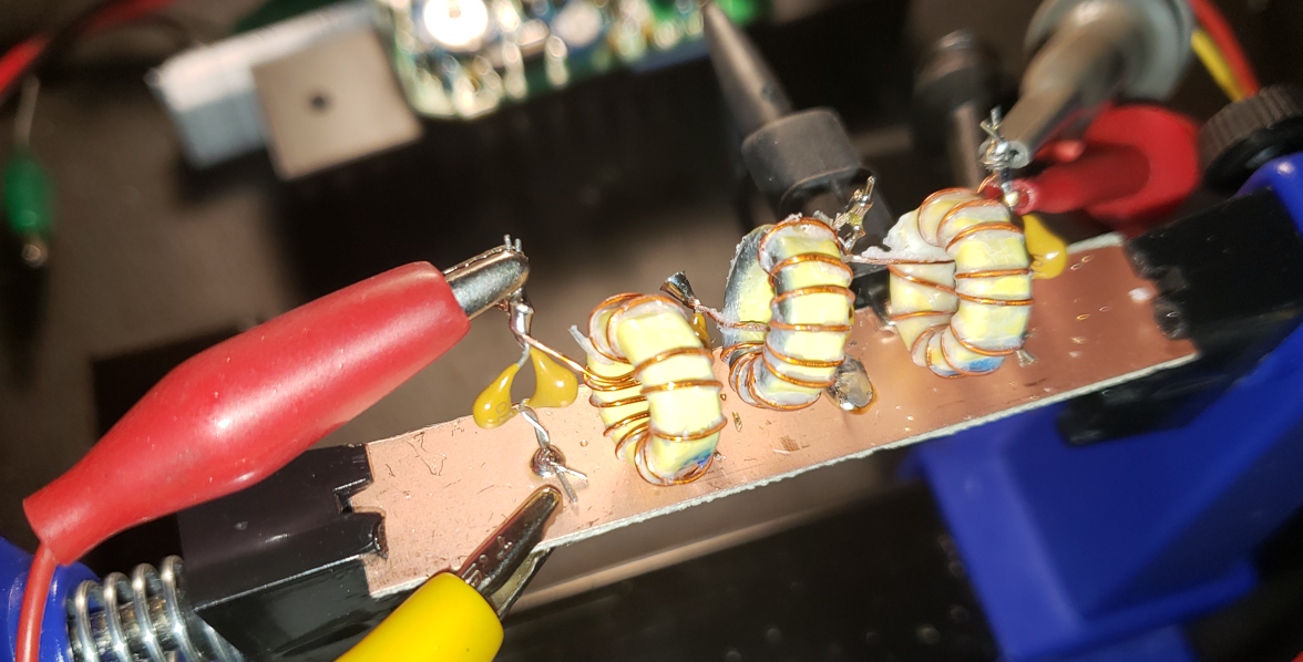
The filter was assembled on a strip of single sided PCB, as shown in the photo below. Click to enlarge.

The full power filter output into a dummy load is shown below.  Click to enlarge. The input voltage is approximately 3.5 Vpp. Frequency is 14.0000 MHz.  Output power is 9.9W.  Gain is about 25 dB.


Sunday, January 15, 2023

QRP Labs 10W PA (3) -- Designing 40m LC Low Pass Filter (Updated)

 To design the 40 m LC filter for the 10W amp output,  I decided to use the 7 pole Chebyshev table found on Page 6-43 of the 1981 ARRL Handbook.  Click the diagram to enlarge.  

The information can also be found in the 1979 QST article "Low-Pass Filters for Amateur Radio Transmitters", by E. E. Wetherhold, W3NQN.  The design for 40 meters supposedly uses standard capacitor values for C1, C3, C5 and C7, but I don't have any 300 pF caps in my parts collection, so I'll use 82 pF plus 220 pF to get close. I have T50-6 cores in my parts store, so I'll them.  The table of parts is: 
  • C1 & C7 -- 300 pF NPO, approximate with 82 pF in parallel with 220 pF
  • C3 & C5 -- 680 pF NPO
  • L2 & L6 -- 1.37 uH, 18T on T50-6 core, using 26 AWG enamel wire
  • L4  -- 1.62 uH,  20T on T50-6 core, using 26 AWG enamel wire
The figure below shows the LTSPICE circuit for simulation (click to enlarge). The AC voltage source is set up with a source impedance of 50 ohm. 

The response of the filter is shown in the plot below (click to enlarge).  The attenuation at the 14 MHz, the lowest possible 2nd harmonic is -40.5 dB.

At the fundamental frequency of 7 MHz, with 10W power at the load, the current through the inductors will be: 

$I_L=\sqrt{10W/50\Omega}= 447 mA$

Using the micrometals.com design page the losses in the core and wiring are predicted to be 100 mW for each core.  This will generate a minor and tolerable 300 mW of loss in the filter. 
 
Some useful LC filter links: